Air conditioner air supply system and control method

An air supply system and air conditioning technology, applied in the field of control, can solve problems such as energy waste and achieve the effect of saving electric energy

Inactive Publication Date: 2014-01-29
诸城福田汽车科技开发有限公司 +1
View PDF2 Cites 7 Cited by
  • Summary
  • Abstract
  • Description
  • Claims
  • Application Information

AI Technical Summary

Problems solved by technology

At present, the air-conditioning air supply system of the painting workshop is: a blower is used to supply air to three different areas at the same time. The three areas are the gluing area, the grinding area and the paint repairing area. There are differe

Method used


Image

  • Air conditioner air supply system and control method
  • Air conditioner air supply system and control method

Examples


Example Embodiment

[0019] Example 1

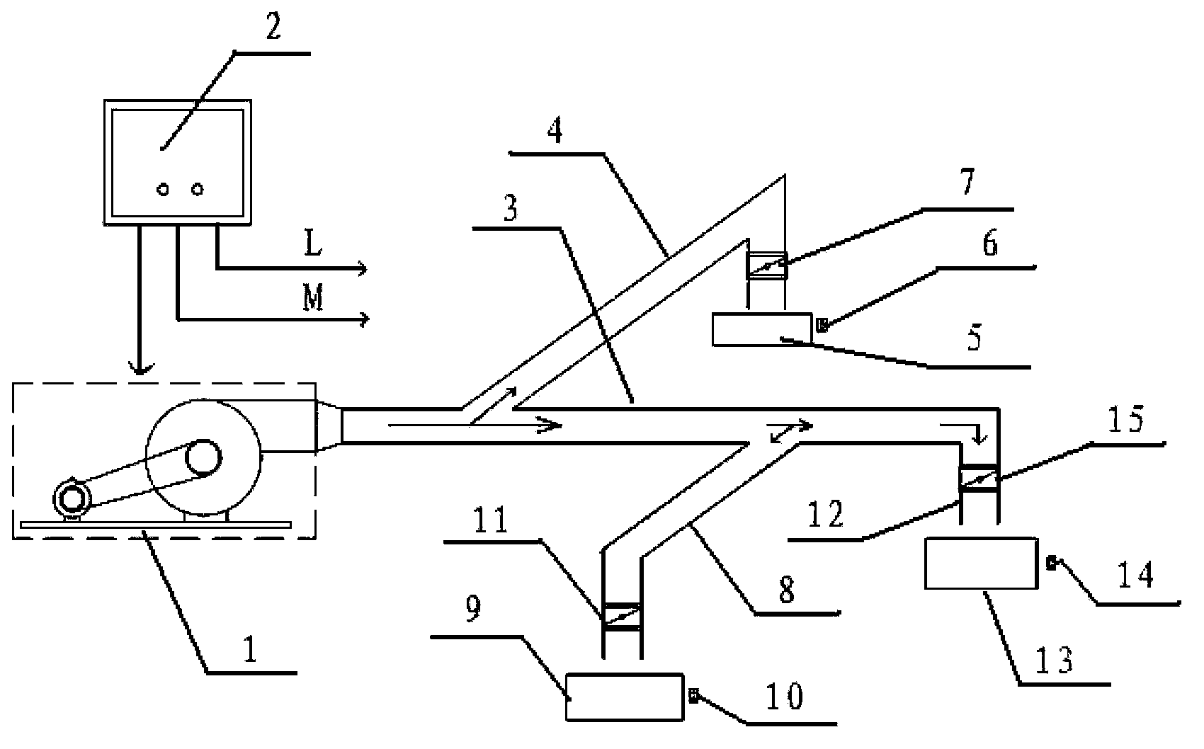
[0020] figure 1 A schematic structural view of the air-conditioning air supply system of this embodiment is shown. With reference to the diagram, this embodiment introduces the structural setting of the air-conditioning air supply system by taking the painting workshop in the vehicle manufacturing process as an example. The painting workshop includes a paint repair area 5 1, grinding area 9 and gluing area 13 three wind-receiving intervals, the air-conditioning air supply system includes a blower 1, and the main air supply channel 3 connected with the air outlet of the blower 1; The air main channel 3 is connected, so as to supply air to the paint repair area 5 through the air supply main channel 3 and the first air supply branch channel 4; the polishing area 9 is connected with the air supply main channel 3 through the second air supply branch channel 8, To send air to the grinding area 9 through the main air supply channel 3 and the second air supply bran...

Example Embodiment

[0026] Example 2

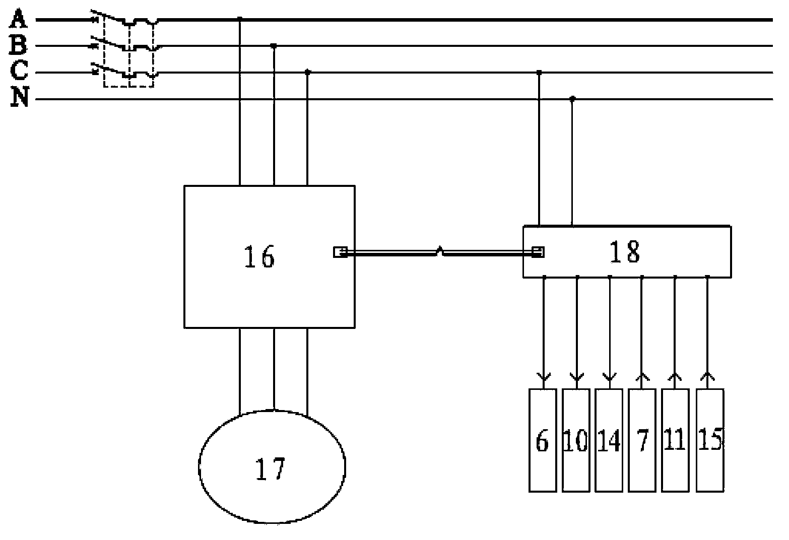
[0027] This embodiment provides an air-conditioning air supply control method based on the air-conditioning air supply system of Embodiment 1, which specifically includes the following process: open the control switch of the wind-receiving section that needs to be blown; the electrical control unit 2 obtains the opening of the control switch signal to control the air blower 1 to operate at the corresponding frequency to supply air, and at the same time control the opening of the air valve in the wind receiving section that needs to be blown; or close the control switch of the wind receiving section that does not need to be blown; the electrical control unit 2 obtains the control The closing signal of the switch controls the air blower 1 to reduce the corresponding frequency to supply air, and at the same time controls the closing of the air valve in the wind-receiving section that does not need to be air-supplied. Wherein, the operating frequency of the air ...


PUM


Abstract

The invention relates to a control technology, and discloses an air conditioner air supply system. The air conditioner air supply system comprises an air supplying machine, a main air supplying channel connected with an air outlet of the air supplying machine, and at least two air receiving spaces communicated with main air supplying channel, wherein air valves are arranged on air inlets of the air receiving spaces, and a control switch is arranged in each air receiving space. The air conditioner air supply system further comprises an electrical control unit which is connected with the air supplying machine, the air valves and the control switches. The electrical control unit controls the air supplying amount of the air supplying machine and on and off of the air valves according to the on-off states of the control switches. The invention further discloses an air conditioner air supplying control method. The frequency of a motor of the air supplying machine can be automatically adjusted according to the amount of the control switches which are turned on, on and off of the air valves are controlled, proper air amounts are supplied according to the number of the air receiving spaces, the purpose of electricity saving is achieved, the structure is simple, and energy is saved.

Description

technical field [0001] The invention relates to control technology, in particular to an air-conditioning air supply system and a control method. Background technique [0002] The vehicle production workshop needs to use the air supply system for air circulation and temperature regulation. At present, the air-conditioning air supply system of the painting workshop is: a blower is used to supply air to three different areas at the same time. The three areas are the gluing area, the grinding area and the paint repairing area. There are differences in the start and stop times of the zones, but no matter whether three zones are working at the same time or only one zone is working, the blower must be turned on, and the blower is always in the same working state, resulting in a large waste of energy. SUMMARY OF THE INVENTION [0003] (1) Technical problems to be solved [0004] The technical problem to be solved by the present invention is to overcome the defects in the prior a...

Claims


Application Information

Patent Timeline
IPC IPC(8): F24F11/04
CPCY02B30/746Y02B30/70
Inventor 林桂先赵子雄王勤俭孔义清
Owner 诸城福田汽车科技开发有限公司
Why Eureka
Try Eureka