
A piston-type rhombic structure optical fiber Bragg grating osmotic pressure sensor and its application method

The technology of a osmotic pressure sensor and a diamond-shaped structure is applied in the field of optoelectronic measuring devices to achieve the effects of easy operation, simple structure, strong anti-electromagnetic interference and corrosion resistance.

Inactive Publication Date: 2016-01-20
KUNMING UNIV OF SCI & TECH
View PDF6 Cites 0 Cited by
  • Summary
  • Abstract
  • Description
  • Claims
  • Application Information

AI Technical Summary

Problems solved by technology

[0003] The invention provides a piston-type rhombic optical fiber Bragg grating osmotic pressure sensor and its use method to solve the problem of real-time on-line monitoring of osmotic pressure

Method used


Image

  • A piston-type rhombic structure optical fiber Bragg grating osmotic pressure sensor and its application method
  • A piston-type rhombic structure optical fiber Bragg grating osmotic pressure sensor and its application method
  • A piston-type rhombic structure optical fiber Bragg grating osmotic pressure sensor and its application method

Examples


Embodiment 1

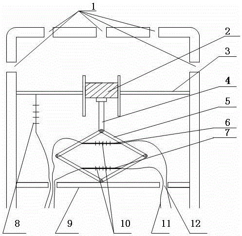
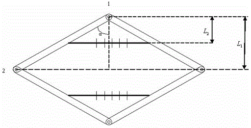
[0048] Embodiment 1: as Figure 1-2 As shown, a piston-type rhombic optical fiber Bragg grating pressure sensor includes a pressure inlet 1, a pressure-bearing piston 2, an upper support frame 3, a pressure guide rod 4, a diamond-shaped pressure transmission structure 5, an upper elastic steel sheet 6, a lower Elastic steel sheet 7, temperature-compensated fiber Bragg grating 8, lower support frame 9, fiber Bragg grating 10, lead-out optical fiber 11, and lead-out hole 12; the pressure inlet 1 is distributed in the pressure transmission chamber, the upper support frame 3, and the lower support frame 9 Welded on the shell, the middle of the upper support frame 3 is connected to the pressure-bearing piston 2, the bottom of the pressure-bearing piston 2 is connected to one end of the pressure guide rod 4, and the other end of the pressure guide rod 4 is connected to the upper end of the diamond-shaped pressure transmission structure 5, and the upper end The elastic steel sheet 6 ...

Embodiment 2

[0052] Embodiment 2: as Figure 1-2 As shown, a piston-type rhombic optical fiber Bragg grating pressure sensor includes a pressure inlet 1, a pressure-bearing piston 2, an upper support frame 3, a pressure guide rod 4, a diamond-shaped pressure transmission structure 5, an upper elastic steel sheet 6, a lower Elastic steel sheet 7, temperature-compensated fiber Bragg grating 8, lower support frame 9, fiber Bragg grating 10, lead-out optical fiber 11, and lead-out hole 12; the pressure inlet 1 is distributed in the pressure transmission chamber, the upper support frame 3, and the lower support frame 9 Welded on the shell, the middle of the upper support frame 3 is connected to the pressure-bearing piston 2, the bottom of the pressure-bearing piston 2 is connected to one end of the pressure guide rod 4, and the other end of the pressure guide rod 4 is connected to the upper end of the diamond-shaped pressure transmission structure 5, and the upper end The elastic steel sheet 6 ...

Embodiment 3

[0064] Embodiment 3: as Figure 1-2 As shown, a piston-type rhombic optical fiber Bragg grating pressure sensor includes a pressure inlet 1, a pressure-bearing piston 2, an upper support frame 3, a pressure guide rod 4, a diamond-shaped pressure transmission structure 5, an upper elastic steel sheet 6, a lower Elastic steel sheet 7, temperature-compensated fiber Bragg grating 8, lower support frame 9, fiber Bragg grating 10, lead-out optical fiber 11, and lead-out hole 12; the pressure inlet 1 is distributed in the pressure transmission chamber, the upper support frame 3, and the lower support frame 9 Welded on the shell, the middle of the upper support frame 3 is connected to the pressure-bearing piston 2, the bottom of the pressure-bearing piston 2 is connected to one end of the pressure guide rod 4, and the other end of the pressure guide rod 4 is connected to the upper end of the diamond-shaped pressure transmission structure 5, and the upper end The elastic steel sheet 6 ...


PUM

PropertyMeasurementUnit
wavelengthaaaaaaaaaa
Sensitivityaaaaaaaaaa

Abstract

The invention relates to an optical fiber Bragg optical grating piston-type rhombus osmotic pressure sensor and a use method thereof, and belongs to the technical field of photoelectron measurement components. The sensor comprises a pressure inlet, a pressure-bearing piston, an upper supporting frame, a pressure guide rod, a rhombus pressure transmitting structure, an upper elastic steel piece, a lower elastic steel piece, a warming optical fiber Bragg optical grating, a lower supporting frame, optical fiber Bragg optical gratings, lead-out optical fibers and lead-out holes. The upper supporting frame and the lower supporting frame are welded to a shell, the middle of the upper supporting frame is connected with the pressure-bearing piston, the bottom of the pressure-bearing piston is connected with one end of the pressure guide rod, the other end of the pressure guide rod is connected with the upper end of the rhombus pressure transmitting structure, the upper elastic steel piece and the lower elastic steel piece are symmetrically fixed to the upper half portion and the lower half portion of the rhombus pressure transmitting structure respectively, one end of the warming optical fiber Bragg optical grating is connected with the upper supporting frame, the lower supporting frame is connected with the lower end of the rhombus pressure transmitting structure, the optical gratings are attached to the upper elastic steel piece and the lower elastic steel piece in an adhesive mode, and the lead-out optical fibers of the optical gratings are led out from the lead-out holes. Real-time on-line monitoring of measured osmotic pressure is achieved.

Description

technical field [0001] The invention relates to a piston-type diamond structure optical fiber Bragg grating osmotic pressure sensor and a using method thereof, belonging to the technical field of optoelectronic measuring devices. Background technique [0002] Due to the extension of mining depth and the expansion of mining range, mine production is developing in depth, the threat of floods is becoming more and more serious, and the task of prevention and control is more difficult. Mine floods seriously threaten the safe production of coal mines and the safety of mine life. Research on the prediction and prevention of coal mine water disasters has been was elevated to an increasingly important position. The pressure of confined water is the most important parameter for studying and predicting water inrush problems, so its real-time monitoring is an important basis for predicting water inrush accidents. At present, electrical sensing technology is widely used in mine geologic...

Claims


Application Information

Patent Timeline
Patent Type & Authority Patents(China)
IPC IPC(8): G01L11/02
Inventor 谢涛李川李英娜赵振纲刘爱莲吴文兵
Owner KUNMING UNIV OF SCI & TECH
Learn More