Testing jig for testing horn

A test stand and speaker technology, used in color TV parts, TV system parts, TVs, etc., can solve the problem of not considering the placement and matching of speakers, inability to test sound effects and sound fields, and inaccurate test results. problem, to achieve the accurate effect of the test structure

Active Publication Date: 2014-01-29
BOE TECH GRP CO LTD +1
View PDF3 Cites 5 Cited by
  • Summary
  • Abstract
  • Description
  • Claims
  • Application Information

AI Technical Summary

Problems solved by technology

However, the existing test methods are usually only to listen to the power supply, without taking into account the placement and collocation of each speaker in the whole machine, and it is impossible to test the sound effects and sound produced by the speakers in the whole machine after they are placed according to the predetermined plan. field for testing
It can be seen that the existing test method cannot simulate the sound effect of each speaker after being placed in the whole machine according to the predetermined plan, and there is a defect that the test effect is not accurate enough

Method used


Image

  • Testing jig for testing horn
  • Testing jig for testing horn
  • Testing jig for testing horn

Examples


Embodiment Construction

[0026] Specific embodiments of the present invention will be described in detail below in conjunction with the accompanying drawings. It should be understood that the specific embodiments described here are only used to illustrate and explain the present invention, and are not intended to limit the present invention.

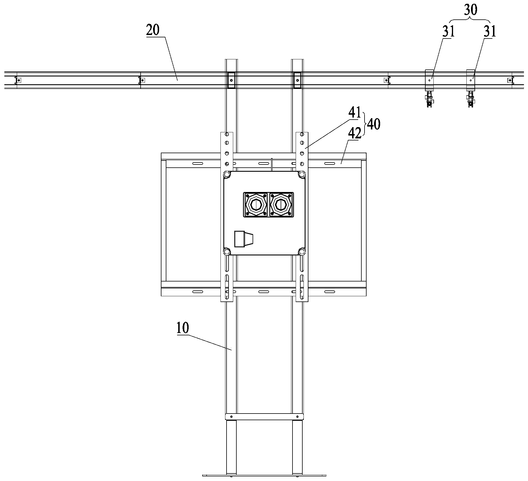
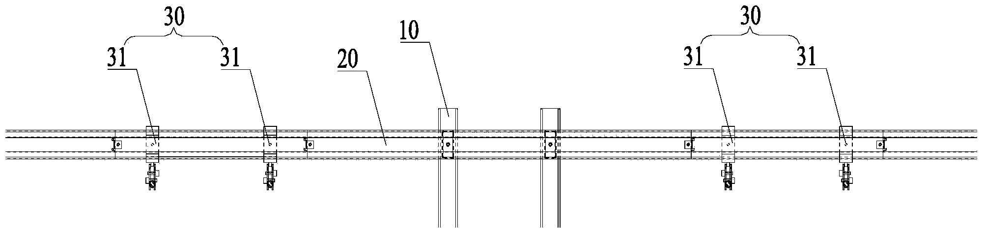
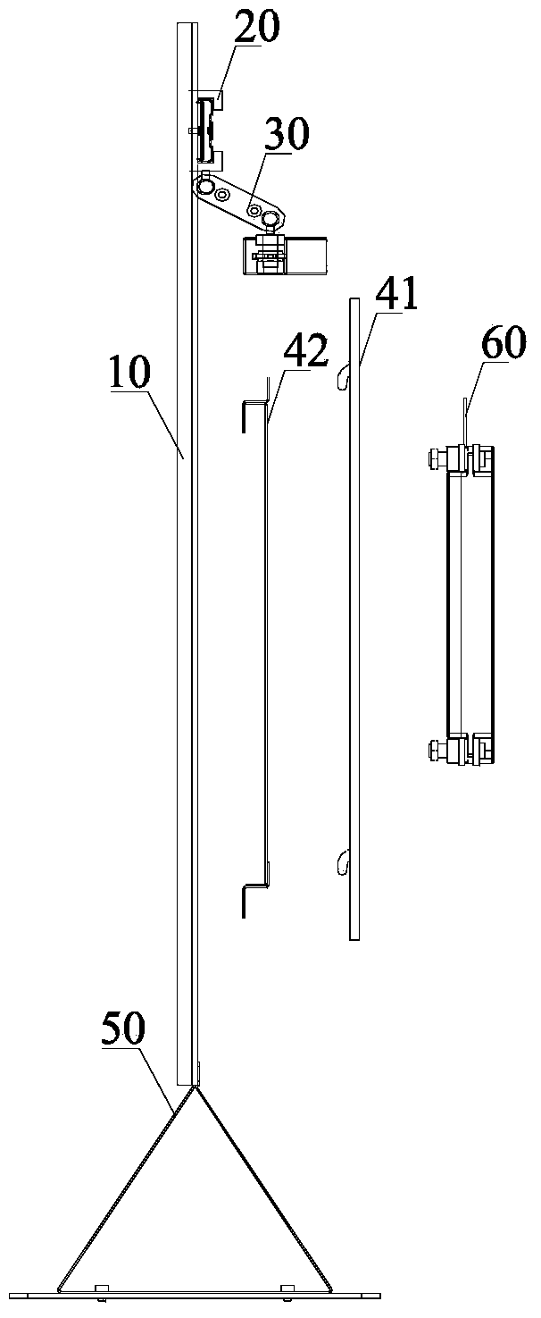
[0027] The invention provides a test frame for horn testing, such as Figure 1 to Figure 6 As shown, the test frame may include a support frame 10 and a cantilever 20 . Wherein, the cantilever 20 can be connected with the support frame 10, the support frame 10 can be placed vertically and support the cantilever 20, and the cantilever 20 is provided with a fixing part 30 for fixing the horn.

[0028] With the above structure, the speaker can be fixed on the fixing member 30 when the speaker is tested, and the connection structure of the support frame 10 and the cantilever 20 can be used to simulate the position of the speaker in the TV set, so that the speaker c...


PUM


Abstract

The invention provides a testing jig for testing a horn. The testing jig comprises a supporting rack and a cantilever. The cantilever is connected with the supporting rack, the supporting rack is vertically arranged and supports the cantilever, and the cantilever is provided with a fixing part used for fixing the horn. The testing jig is provided with the supporting rack and the cantilever, so the position of the horn in a television set can be simulated, a realer sound production effect of the horn of the television set can be obtained in a test, and the test structure can be more accurate.

Description

technical field [0001] The invention relates to the technical field of horn testing, in particular to a test frame for horn testing. Background technique [0002] For TV, in addition to its picture display quality, the sound effect of TV is also an important factor affecting consumer experience. Especially in today's flat-panel TV field, liquid crystal display has become the mainstream solution of display technology. The structural design of the TV set is getting thinner and thinner, and the internal space is limited. Therefore, there are more stringent requirements for the selection and placement of speakers. . [0003] When designing the structure of the TV set, the speaker is usually tested to test the sound effect of the speaker. However, the existing test methods are usually only to listen to the power supply, without taking into account the placement and collocation of each speaker in the whole machine, and it is impossible to test the sound effects and sound produce...

Claims


Application Information

Patent Timeline
Patent Type & Authority Applications(China)
IPC IPC(8): H04R29/00H04N5/64
Inventor 李鹏
Owner BOE TECH GRP CO LTD
Why Eureka
Try Eureka