
A Calibration Method for 3D Reconstruction System

A calibration method and 3D reconstruction technology, applied in the calibration field of 3D reconstruction system, can solve the problems of slow speed, unbearable acquisition efficiency, damage to the measured object, etc., and achieve the effect of simple and convenient operation, fast calculation speed and low cost

Inactive Publication Date: 2016-06-29
CHONGQING ANZUANLI TECH
View PDF4 Cites 0 Cited by
  • Summary
  • Abstract
  • Description
  • Claims
  • Application Information

AI Technical Summary

Problems solved by technology

Contact scanning uses a contact probe. The probe needs to be in contact with the measured object during measurement. Although the measurement accuracy is very high, and the measurement is completely unaffected by the properties of the object’s surface reflection, color, etc., because the distance measuring probe needs to touch the measured object The surface of the object needs to generate a certain pressure, so it will cause a certain degree of damage to the measured object, and the scanning needs to be measured point by point, the speed is slow, and the acquisition efficiency is unbearable; and because the distance measuring probe needs to contact the measured object and generate Therefore, there are certain requirements for the material of the object to be measured, and only objects with relatively hard surface materials can be measured.

Method used


Image

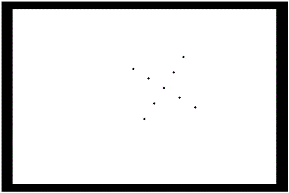
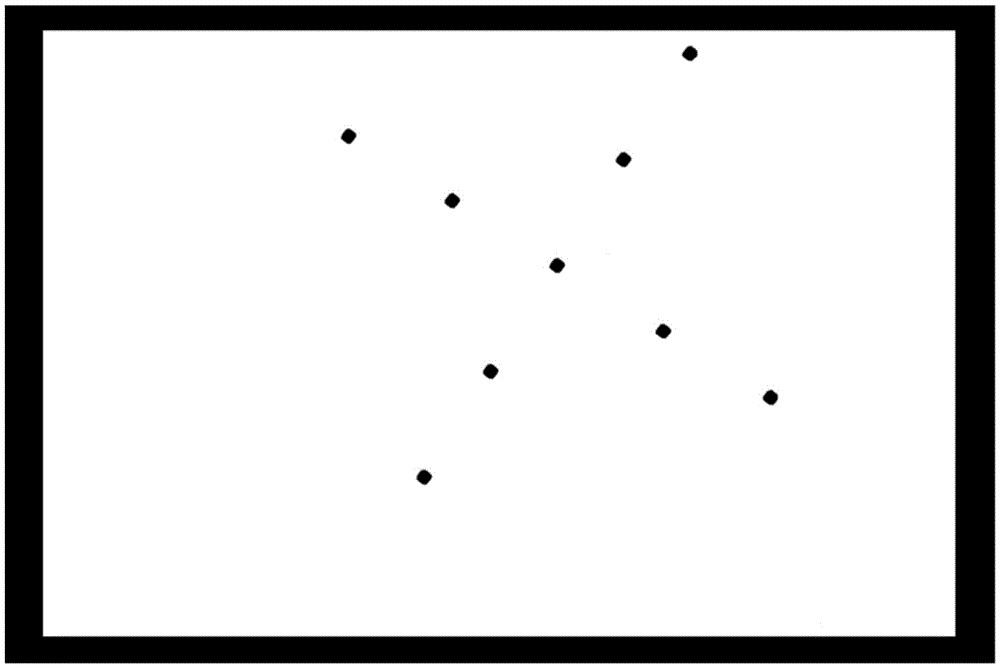
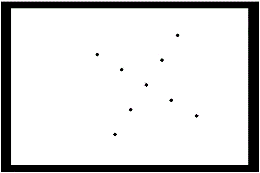
  • A Calibration Method for 3D Reconstruction System
  • A Calibration Method for 3D Reconstruction System
  • A Calibration Method for 3D Reconstruction System

Examples


Embodiment Construction

[0023] The advantages of the present invention will be further elaborated below in conjunction with the accompanying drawings and specific embodiments.

[0024] Generally speaking, a 3D reconstruction system includes a light projection device and a light sensing device. In operation, a grating pattern is generated by the light projection device, and the pattern is projected onto a target object. Since the surface of the target object is not smooth, the pattern projected on the target object is different from the original pattern, thus forming a projected pattern on the target object. For example, when the surface of the object has protrusions, the pattern projected on the protrusions will be brighter than the pattern projected on the flat surface due to the principle of light reflection. Similarly, when the surface of the object has depressions, the pattern projected on the depressions The pattern will be less bright than a pattern projected on a flat surface. Utilizing the ...


PUM


Abstract

The invention discloses a calibration method, which is to obtain the position coordinates of a calibration image on the film of a light projection device; record the projection images projected by the light projection device at the first focal length and the second focal length, and form a first recorded image and a second recorded image , analyze the first recorded image and the second recorded image, and calculate the coordinates of the optical center of the light projection device and the coordinates of the calibration image; Calculate the focal length of the light projection device according to the relative distance of the projection screen; fix the light projection device at the second position, and calculate the focal length of the light sensing device based on the projected image and the recorded image. After adopting the above technical solution, the parameter values ​​of the light projection device and the light sensing device can be accurately calibrated in a simple manner.

Description

technical field [0001] The invention relates to the field of optical three-dimensional measurement, in particular to a calibration method for a three-dimensional reconstruction system. Background technique [0002] With the development of 3D printing technology, it has important practical significance and research value to quickly and accurately obtain 3D data of objects and perform 3D modeling. Generally, there are three ways for people to obtain a 3D model of an object: the first way is to use modeling software, such as AutoCAD, to construct a 3D model close to the real object; the second way is to use a series of images or The third way is to scan the surface of the object through a 3D scanning device to obtain the 3D information of the object to reconstruct the 3D model. [0003] Among them, the third method is the 3D scanning method. Compared with the first two methods, it can obtain more accurate 3D data, and is suitable for modeling applications with certain precisio...

Claims


Application Information

Patent Timeline
Patent Type & Authority Patents(China)
IPC IPC(8): G06T7/00G06T17/00
Inventor 王凤麟杨树臣王小宇
Owner CHONGQING ANZUANLI TECH
Learn More