Grab, continuous wall hydraulic grab grooving machine and grab operation method

The technology of grab bucket and bucket shell is applied in the field of hydraulic grab bucket forming machine for continuous wall, which can solve the problems of long time, limited scraping area, and difficulty in scraping the soil out.

Active Publication Date: 2016-02-03
SHANGHAI ZOOMLION HEAVY IND PILING MACHINERYCO +1
View PDF3 Cites 0 Cited by
  • Summary
  • Abstract
  • Description
  • Claims
  • Application Information

AI Technical Summary

Problems solved by technology

[0005] During the opening and closing process of the grab shell 30, due to the high viscosity of some rock and soil layers, it often adheres to the inner wall of the grab shell 30. The mud scraper 20 with the above-mentioned hollow structure has a limited scraping area and is very It is difficult to scrape out the soil at one time, and it takes several times to open and close the grab shell 30 to drain the soil, which is time-consuming and labor-intensive
In addition, sometimes before the grab shell 30 discharges soil, it is necessary to discharge mud and accumulated water out of the grab shell 30 to discharge the soil. However, the existing mud scraper 20 does not have the function of squeezing water, and the accumulated water in the grab shell 30 It can only flow out freely by gravity, and it takes a long time

Method used


Image

  • Grab, continuous wall hydraulic grab grooving machine and grab operation method
  • Grab, continuous wall hydraulic grab grooving machine and grab operation method
  • Grab, continuous wall hydraulic grab grooving machine and grab operation method

Examples


Embodiment approach

[0056] According to a preferred embodiment of the present invention, the grab operation method also includes a soil discharge step:

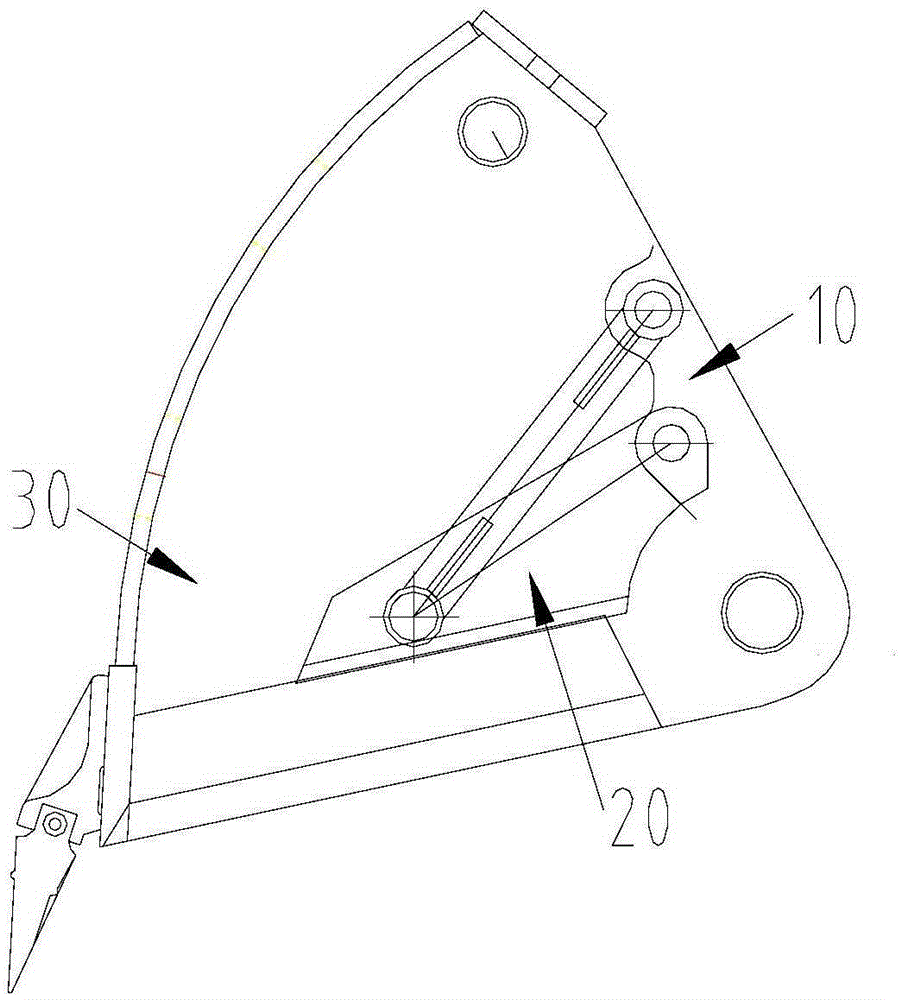
[0057] S20: The grab shell 30 starts to open to remove the grabbed rock and soil, and the residual rock and soil in the grab shell 30 pushes the mud scraper 20 to rotate to abut against the first stopper 14; specifically, when the grab When carrying out soil removal operations, such as Figure 7d As shown, the grab shell 30 along Figure 7d Rotate clockwise, in the process of gradually opening, the rock and soil in the grab shell 30 will be discharged from the grab shell 30 under the action of its own gravity. However, some rocks and soils in the grab shell 30 will adhere to the inner wall of the grab shell and fail to be discharged in time. These rocks and soils that have not been discharged in time also rotate clockwise, so that the mud scraper 20 is pushed by the adhesion force of the rocks and soils. down, along Figure 7d clockwise rotat...


PUM


Abstract

The invention provides a grab bucket, a continuous wall hydraulic grab bucket grooving machine and a grab bucket working method. The grab bucket comprises a grab bucket base, a grab bucket shell and a scraper, wherein the grab bucket shell is connected to the grab bucket base in a pivot mode, and the scraper is located in the grab bucket shell; the scraper includes a scraper body which is of a platy structure; when the grab bucket shell is in a fully open state, the scraper body is connected to the grab bucket base in a pivot mode in the form of at least covering a part of a soil inlet of the grab bucket shell, so that the scraper can rotate freely when the grab bucket grabs soil; in this way, the scraper will not cover the soil inlet of the grab bucket shell, and therefore the soil feeding amount of the grab bucket shell is not affected; furthermore, the scraper body is of the platy structure, so that the scraping area of the scraper is greatly increased when the grab bucket discharges the soil, and working efficiency of the grab bucket can be improved. Besides, in the working process of the grab bucket, the scraper can further compress ground for squeezing and draining, so that accumulated water in the grab bucket does not need to be drained by utilizing extra tools and time, the working efficiency of the grab bucket can be further improved, and the use cost of the grab bucket is saved.

Description

technical field [0001] The invention relates to the technical field of engineering machinery, in particular to a grab and a continuous wall hydraulic grab slotting machine with the grab, and a grab operation method. Background technique [0002] Grabs are widely used in the modern construction industry. In particular, the grab is mainly used in an underground diaphragm wall hydraulic grab slotting machine in the field of engineering machinery. A grab usually includes a grab seat, a grab shell and a mud scraper. The grab shell is connected to the grab seat, and the mud scraper is installed in the grab shell. During the working process of the grab, the grab shell needs to be opened and closed. Close to grab soil and carry it elsewhere for discharge. [0003] At present, the mud scraper used in the grab is usually fixed, that is, the mud scraper is fixed on the grab seat, in order not to affect the amount of soil entering the grab shell, and to eliminate the stress caused by ...

Claims


Application Information

Patent Timeline
Patent Type & Authority Patents(China)
IPC IPC(8): E02F5/02E02F5/14
Inventor 乔国华方东辉朱长林
Owner SHANGHAI ZOOMLION HEAVY IND PILING MACHINERYCO
Why Eureka
Try Eureka