Involute spherical gear transmission pair
A technology of involute gears and ball gears, which is applied in the direction of gear transmissions, transmissions, belts/chains/gears, etc., can solve the problem of no transmission principle error, etc., and achieve the effect of ensuring machining accuracy
- Summary
- Abstract
- Description
- Claims
- Application Information
AI Technical Summary
Problems solved by technology
Method used
Image

Examples
specific Embodiment approach 1
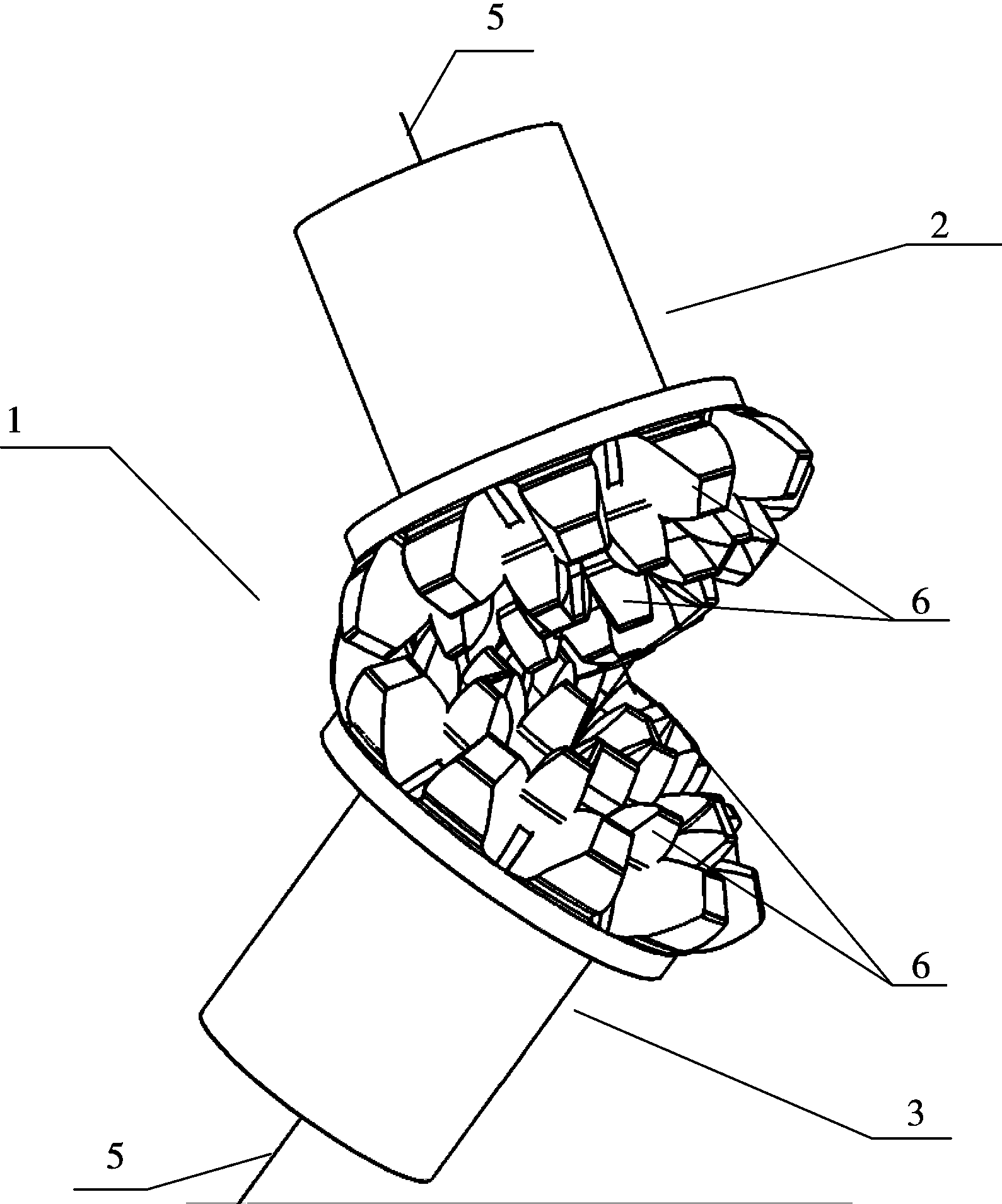
[0054] Specific implementation mode one: combine figure 1 , figure 2 , image 3 , Figure 4 , Figure 5 , Image 6 and Figure 7 To describe this embodiment in detail, the ball gear transmission pair 1 of this embodiment includes a ball gear 2 with a central convex tooth 7 and a ball gear 3 with a central groove 8. The ball gear 2 and the ball gear 3 have a spherical crown 4 and an axis 5 , there is an involute gear tooth 6 on the spherical crown 4, the position of the spherical center of the spherical gear 2 and the spherical center of the spherical gear 3 are relatively fixed, the joint spherical surface of the spherical gear 2 is tangent to the joint spherical surface of the spherical gear 3, and the spherical center of the spherical gear 2 The distance to the center of the ball gear 3 is equal to the sum of the radius of the ball gear 2 and the radius of the ball gear 3 passing through the tangent point of the pitch sphere of the ball gear 2 and the pitch sphere of t...
specific Embodiment approach 2
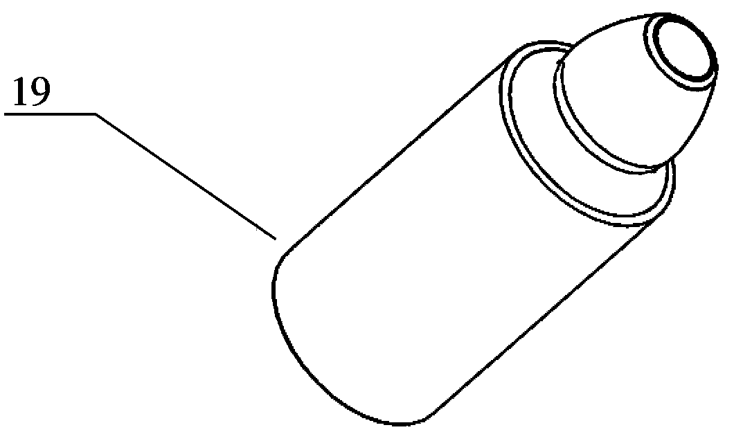
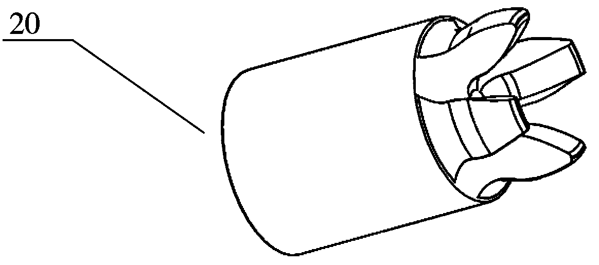
[0058] Specific implementation mode two: combination figure 2 , image 3 , Figure 4 , Figure 5 , Figure 8 , Figure 9 , Figure 10 , Figure 11 , Figure 12 , Figure 13 Figure 14 and Figure 15 To describe this embodiment in detail, the ball gear 17 of the ball gear transmission pair of this embodiment is made of a central convex tooth 19, a first gear ring 20, a second gear ring 21, a third gear ring 22, and a fourth tooth ring. The ring 23 and the fifth gear ring 24 are formed by removing the interfering parts and fixing them together. The ball gear 18 is formed by removing the interfering parts of the first ring gear 20, the second ring gear 21, the third ring gear 22, the fourth ring gear 23 and the fifth ring gear 24 which are made separately.
[0059] Do not have tooth core 16 in ball gear 7, ball gear 8 in ball gear 17, ball gear 18 made with this method.
[0060] The central protruding tooth 19, the first ring gear 20, the second ring gear 21, the thi...
specific Embodiment approach 3
[0061] Specific implementation mode three: combination Figure 16 , Figure 17 , Figure 18 , Figure 32 ,and Figure 33 To describe this embodiment in detail, the ball gear transmission pair in this embodiment is a helical gear ball gear transmission pair 25, which includes a ball gear 26 with central convex teeth and a ball gear 27 with central grooves. The tooth length direction of the gear teeth 28 on the ball gear 26 and the ball gear 27 is different from the direction of the meridian, but a spiral with a certain angle with the direction of the meridian. Curves like curves. The rotation direction of the curve in the tooth length direction of the gear teeth 28 on the ball gear 26 is opposite to the rotation direction of the curve in the tooth length direction of the gear teeth 28 on the ball gear 27 .
PUM
 Abstract
Description
Claims
Application Information