Large-caliber lens system

A lens system and large-aperture technology, applied in optical components, instruments, optics, etc., can solve the problems of increased lens cost and inability to correct coma aberration, and achieve the effect of fewer lenses and good spherical aberration

Active Publication Date: 2014-02-12
RICOH IMAGING COMPANY
View PDF9 Cites 19 Cited by
  • Summary
  • Abstract
  • Description
  • Claims
  • Application Information

AI Technical Summary

Problems solved by technology

However, since an aspheric lens is used in the last lens (the positive lens closest to the image side in the rear lens group), the rearmost shape of the lens has a turning point, which requires high-precision forming technology, resulting in an increase in lens cost
Also, it doesn't correct for coma aberration well

Method used


Image

  • Large-caliber lens system
  • Large-caliber lens system
  • Large-caliber lens system

Examples


Embodiment 1

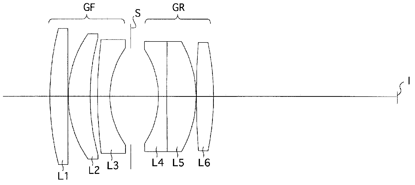
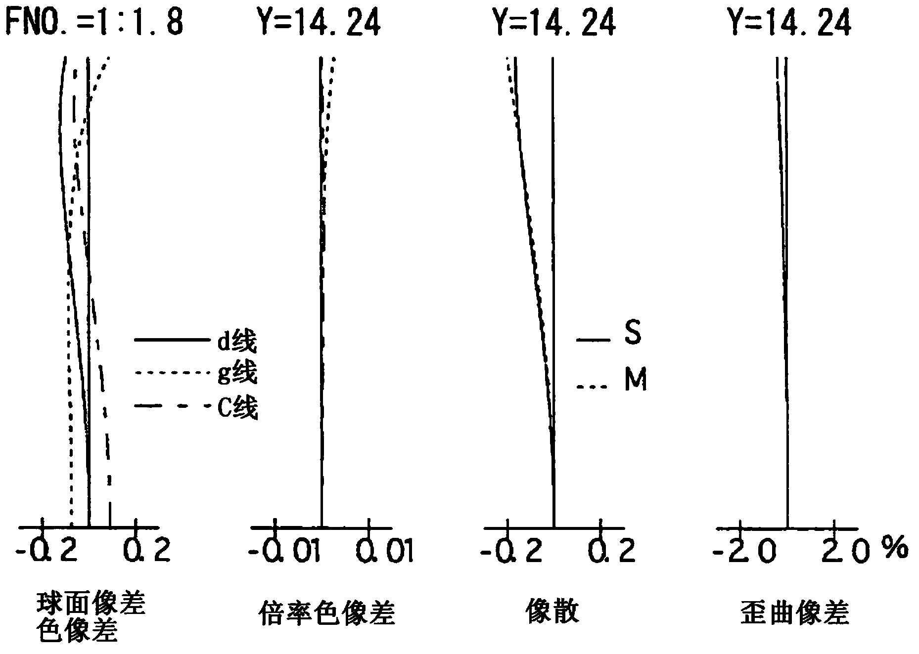
[0127] Figure 1-Figure 3 And Table 1-Table 2 show numerical embodiment 1 of the large-aperture lens system of the present invention. figure 1 is the lens structure diagram when focusing at infinity, figure 2 is its longitudinal aberration diagram, image 3 is its lateral aberration diagram. Table 1 is surface data, and Table 2 is various data.

[0128] The large-aperture lens system of the present numerical example 1 includes, in order from the object side, a front lens group GF having positive diopter, an aperture S, and a rear lens group GR having positive diopter. I is the image plane.

[0129] The front lens group GF, in order from the object side, includes: the first lens (positive meniscus lens convex toward the object side) L1, which has a positive diopter; the second lens (positive meniscus lens convex toward the object side) L2 , which has a positive diopter; and the third lens (a negative meniscus lens convex toward the object side) L3, which has a negative di...

Embodiment 2

[0136] Figure 4-Figure 6 And Table 3-Table 4 show numerical embodiment 2 of the large-aperture lens system of the present invention. Figure 4 is the lens structure diagram when focusing at infinity, Figure 5 is its longitudinal aberration diagram, Image 6 is its lateral aberration diagram. Table 3 is surface data, and Table 4 is various data.

[0137] The lens structure of the present numerical example 2, except that the fourth lens L4 is a negative meniscus lens convex toward the image side, and the fifth lens L5 is a positive meniscus lens convex toward the image side, is the same as The structure of Numerical Example 1 is the same.

[0138] (table 3)

[0139]

[0140] (Table 4)

[0141]

[0142]

Embodiment 3

[0144] Figure 7-Figure 9 And Table 5-Table 6 show numerical embodiment 3 of the large-aperture lens system of the present invention. Figure 7 is the lens structure diagram when focusing at infinity, Figure 8 is its longitudinal aberration diagram, Figure 9 is its lateral aberration diagram. Table 5 is surface data, and Table 6 is various data.

[0145] The lens structure of Numerical Example 3 is the same as that of Numerical Example 2.

[0146] (table 5)

[0147]

[0148] (Table 6)

[0149]

[0150]


PUM


Abstract

The invention aims to provide a bright large-caliber lens system, whose f-number (aperture ratio) is about 1.8. The lens pieces are in a small number, and are capable of obtaining good optical performance through well correcting the spherical aberration of coma, astigmatism, and optical axis. The large-caliber lens system comprises a front lens set having a positive diopter, an aperture, and a rear lens set having a positive diopter. The front lens set comprises a first lens having a positive diopter, a second lens having a positive diopter, and a third lens having a negative diopter in order. The rear lens set comprises a fourth lens having a negative diopter, a fifth lens having a positive diopter, and a sixth lens having a positive diopter. The large-caliber lens system meets the following conditional expression (1) and (2): 1.03<L2f / f<1.83; 0.3<(r5-r4) / (r5+r4)<0.8, wherein L2f is the focus of the second lens; f is the focus of the whole system; r4 is the radius of curvature of the side face of the second lens; r5 is the radius of curvature of the side face of the third lens.

Description

technical field [0001] The invention relates to a large diameter lens system. Background technique [0002] As bright photographic lens systems for photography, Gaussian photographic lens systems are often used, and research and development are being carried out with the goals of larger diameter, smaller size, higher performance, lower cost, and the like. [0003] For example, in Patent Documents 1-4, a Gaussian photographic lens system is disclosed. The front lens group and the rear lens group are opposite to each other with the diaphragm interposed, and the front lens group is composed of three lenses with positive and negative diopters. The rear lens group consists of three lenses with negative and positive diopters. [0004] However, the photographic lens system described in Patent Document 1 cannot properly correct astigmatism and spherical aberration on the optical axis because the refractive power of the second positive lens in the front lens group is not suitable. ...

Claims


Application Information

Patent Timeline
Patent Type & Authority Applications(China)
IPC IPC(8): G02B13/00G02B27/00
Inventor 加藤浩司
Owner RICOH IMAGING COMPANY
Why Eureka
Try Eureka