An axial variable magnification three-field long-wave infrared imaging optical system

A technology of long-wave infrared and imaging optics, which is applied in optics, optical components, instruments, etc., can solve the problems such as the difficulty of correcting aberrations, and achieve the effect of small investment, simple structure, and fewer lenses

Active Publication Date: 2018-01-09
LUOYANG INST OF ELECTRO OPTICAL EQUIP OF AVIC
View PDF2 Cites 0 Cited by
  • Summary
  • Abstract
  • Description
  • Claims
  • Application Information

AI Technical Summary

Problems solved by technology

[0002] The implementation methods of infrared three-field continuous zoom optical system at home and abroad are divided into radial zoom mode and axial zoom mode, and the axial zoom mode is based on different positions of the zoom mirror and compensation mirror on the optical axis. Realizing the conversion of three fields of view has the advantages of small size and light weight, but it is difficult to correct aberrations in the actual design of the axial zoom optical system with a zoom ratio greater than 20 times

Method used


Image

  • An axial variable magnification three-field long-wave infrared imaging optical system
  • An axial variable magnification three-field long-wave infrared imaging optical system
  • An axial variable magnification three-field long-wave infrared imaging optical system

Examples


Embodiment Construction

[0018] The present invention will be described in further detail below in conjunction with the accompanying drawings.

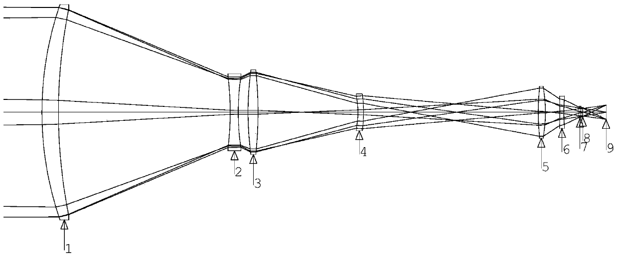
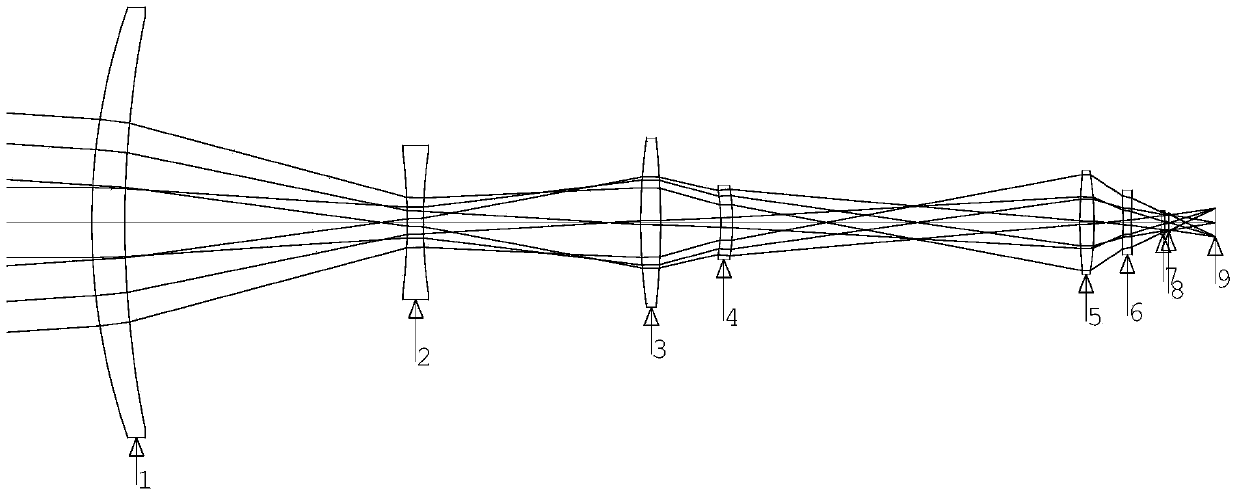
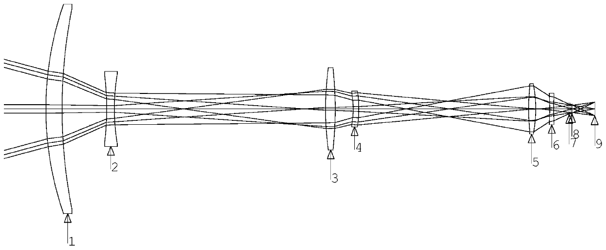
[0019] The axial variable magnification three-field long-wave infrared imaging optical system provided by the present invention adopts a secondary imaging configuration to converge and image long-wave infrared radiation, so as to effectively compress the aperture of the objective lens. like figure 1 , 2 Or as shown in 3, the axial variable magnification three-field-of-view long-wave infrared imaging optical system includes an objective lens 1, a variable magnification mirror 2, a compensating mirror 3, a focusing mirror 4, and a converging lens group that are sequentially arranged on the same optical axis from the object side to the image side, Wherein, the converging lens group is composed of a converging mirror 5 and a converging mirror 6 arranged coaxially in sequence. Figure 1-3 Parts 7, 8 and 9 in are components of the detector, which have nothing to ...


PUM


Abstract

The invention relates to an axial-zooming tri-view-field long-wave infrared imaging optical system. The system comprises an objective lens, a zooming lens, a compensating lens, a focusing lens and a converging lens set which are sequentially arranged in the same optical axis from the object space to the image space, and the surface, close to the image space, of the compensating lens adopts a diffraction surface; design index parameters of the optical system are as followed: working waveband ranges from 7700 nm to 9500 nm, the focal distance of the system in a large view field is 22 mm, the focal distance of the system in a middle view field is 92 mm, and the focal distance of the system in a small view field is 550 mm; the working environment temperature ranges from minus 40 DEG C to 60 DEG C. According to the axial-zooming tri-view-field long-wave infrared imaging optical system, switching among the three view fields is achieved by axially moving the zooming lens and the focusing lens, and the zooming ratio can reach 25 times; in addition, by axially regulating the position of the focusing lens, focal point drifting on the image surface due to the temperature changes can be compensated, it is guaranteed that the image quality is not changed along with the temperature, and therefore the high-low temperature environmental suitability of the optical system is good.

Description

technical field [0001] The invention relates to an axial variable magnification three-field long-wave infrared imaging optical system. Background technique [0002] The implementation methods of infrared three-field continuous zoom optical system at home and abroad are divided into radial zoom mode and axial zoom mode, and the axial zoom mode is based on different positions of the zoom mirror and compensation mirror on the optical axis. Realizing the conversion of three fields of view has the advantages of small size and light weight, but it is difficult to correct aberrations in the actual design of an axial zoom optical system with a zoom ratio greater than 20 times. Contents of the invention [0003] The object of the present invention is to provide an axial variable magnification three-field long-wave infrared imaging optical system. [0004] In order to achieve the above object, the solution of the present invention includes an axial variable magnification three-fiel...

Claims


Application Information

Patent Timeline
Patent Type & Authority Patents(China)
IPC IPC(8): G02B15/14G02B13/14G02B1/00
CPCG02B1/00G02B13/14G02B15/14
Inventor 赵珩兰卫华
Owner LUOYANG INST OF ELECTRO OPTICAL EQUIP OF AVIC
Why Eureka
Try Eureka