

Combined mutual inductor
A technology of transformers and current transformers, applied in the field of transformers, can solve problems such as troublesome installation, and achieve the effect of simplifying the difficulty
Inactive Publication Date: 2014-02-12
JIANGSU FEAL ELECTRICAL APPLIANCES
View PDF6 Cites 4 Cited by
- Summary
- Abstract
- Description
- Claims
- Application Information
AI Technical Summary
Problems solved by technology
[0003] The disadvantage of the existing technology is that multiple plugs need to be used in the controller, and only a separate connecting wire can be used to install it inside the switch, which is troublesome to install.
Method used
View moreImage
Smart ImageViewing Examples

Examples
Embodiment Construction
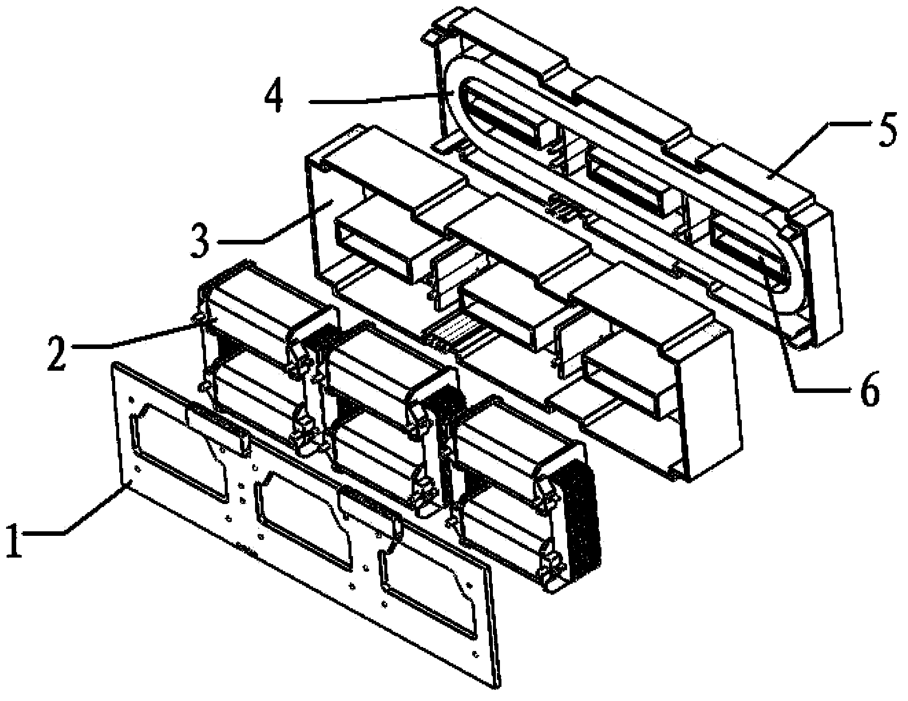
[0010] like figure 1 As shown, a combined circuit transformer of the present invention is characterized in that a circuit board 1, a current transformer module and a leakage transformer module are arranged sequentially from top to bottom, and the current transformer module is composed of a current transformer coil 2 and a current transformer The leakage transformer shell 3 is combined and filled with glue, and the leakage transformer module is formed by combining the leakage transformer coil 4 and the leakage transformer shell 5 with glue.
[0011] A copper buckle 6 for taking power from the outside is arranged inside the earth leakage transformer shell 5 .
Login to View More PUM
 Abstract
The invention discloses a combined circuit mutual inductor. The combined circuit mutual inductor is provided with a circuit board, a current transformer module and an electric leakage mutual inductor module, all of which are arranged sequentially from top to bottom, wherein the current transformer module is formed by combining and glue-filling a current transformer coil and a current transformer outer shell, and the electric leakage mutual inductor module is formed by combining and glue-filling an electric leakage manual inductor coil and an electric leakage mutual inductor outer shell. The combined circuit mutual inductor simplifies installation difficulty, fully utilizes universal rate of various mutual inductors, and highly integrates functions of the mutual inductor.
Description
technical field [0001] The invention relates to a transformer, in particular to a combined transformer. Background technique [0002] The existing technical solution in the market is that the current transformer, the leakage transformer, and the electricity are all connected to the controller through a separate connection. [0003] The disadvantage of the prior art is that multiple plugs need to be used in the controller, which can only be installed inside the switch using a separate connecting wire, and the installation is troublesome. Contents of the invention [0004] The purpose of the present invention is to provide a combined circuit transformer aiming at the defects existing in the prior art. [0005] In order to achieve the above object, the present invention adopts the following technical solutions: [0006] A combined circuit transformer of the present invention is characterized in that a circuit board, a current transformer module and a leakage transformer mod...
Claims
Login to View More Application Information
Patent Timeline
 Patent Type & AuthorityApplications(China)
IPC IPC(8): H01F38/20H01F38/30
Inventor杜建中姚相东韦天亮
OwnerJIANGSU FEAL ELECTRICAL APPLIANCES