A message control method, system and node during aggregation link switching

A technology of aggregation link and control method, which is applied in the field of packet control during aggregation link switching, can solve the problems of unable to guarantee the forwarding of Marker protocol packets, and unable to make a Marker protocol reply to the peer end, so as to ensure orderly The effect of transmission

Inactive Publication Date: 2018-07-20
ZTE CORP
View PDF4 Cites 0 Cited by
  • Summary
  • Abstract
  • Description
  • Claims
  • Application Information

AI Technical Summary

Problems solved by technology

[0009] The above process is not applicable to the case where the endpoint includes multiple nodes, because at this time the aggregation link switching may be across nodes. If a node receives a Marker protocol message, such as the Marker PDU in the above process, the node cannot guarantee Other nodes in the endpoint where you are located have completed the forwarding of the Marker protocol message, so you cannot make a Marker protocol reply to the peer

Method used


Image

  • A message control method, system and node during aggregation link switching
  • A message control method, system and node during aggregation link switching
  • A message control method, system and node during aggregation link switching

Examples


Embodiment 1

[0104] like Figure 4 As shown, nodes A, B and nodes C, D form a link aggregation group through aggregation links 1, 2.

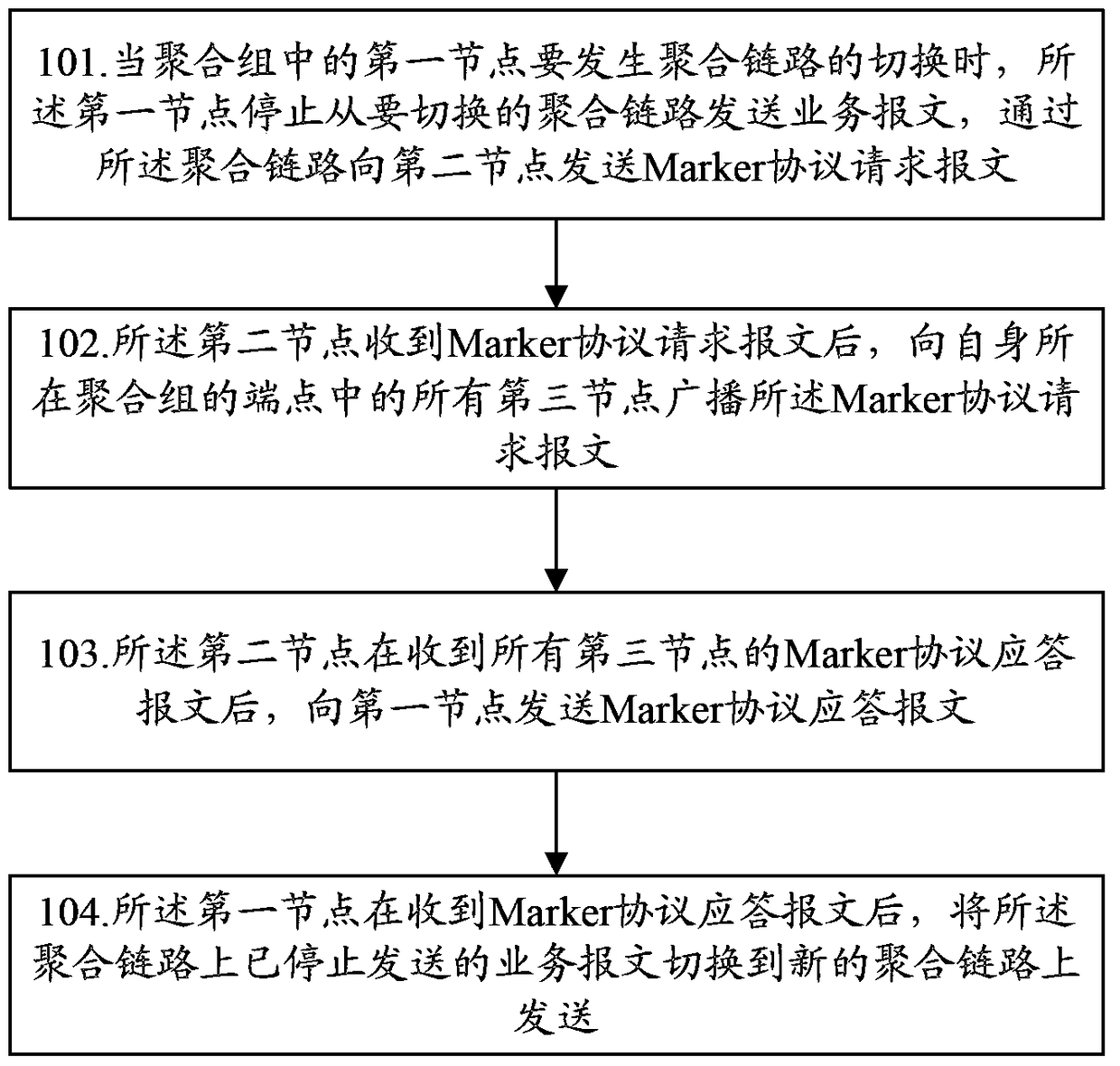
[0105] Assume that in general, there is a group of service packets sent on the aggregated link 1 in the link aggregation group. For some reasons, such as the aggregated link 1 needs to be isolated from the aggregation group, or a new port is added to the aggregation group , or the distributor decides to redistribute the service packets on the aggregation link 1 on a group of ports, etc., the group of service packets needs to be switched from the aggregation link 1. This embodiment realizes the message control method when the aggregation link is switched, such as Figure 5 As shown, the method includes the following steps:

[0106] Step 201: Node D stops sending messages from aggregation link 1, sends a Marker protocol request message to peer node A through aggregation link 1, and starts timer 1;

[0107] Step 202: After node A receives the Marker protoco...

Embodiment 2

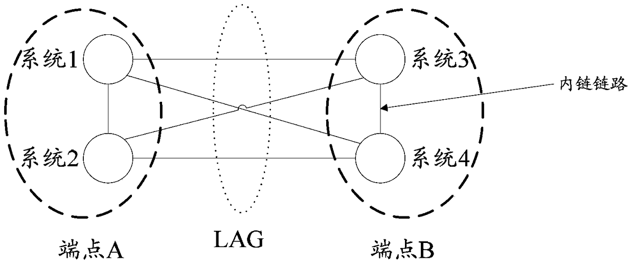
[0116] like Figure 6 As shown, both ends of the aggregation group are composed of multiple nodes, one end has nodes A, B, and node E, and the other end has nodes C, D, and node F. A link is formed by aggregation links 1, 2, and 3 aggregation group.

[0117] Assume that in general, there is a group of service packets sent on the aggregated link 1 in the link aggregation group. For some reasons, such as the aggregated link 1 needs to be isolated from the aggregation group, or a new port is added to the aggregation group , or the distributor decides to redistribute the service packets on the aggregation link 1 on a group of ports, etc., the group of service packets needs to be switched from the aggregation link 1. This embodiment realizes the message control method when the aggregation link is switched, such as Figure 7 As shown, the method includes the following steps:

[0118] Step 301: Node D stops sending messages from aggregation link 1, sends a Marker protocol request ...


PUM


Abstract

The present invention discloses a message control method, system and node when an aggregated link is switched. The first node stops sending service messages from the aggregated link to be switched, and sends a Marker protocol to the second node through the aggregated link. request message; after the second node receives the Marker protocol request message, it broadcasts the Marker protocol request message to all the third nodes in the endpoints of the aggregation group where itself; the second node receives all the third nodes After receiving the Marker protocol response message, the first node sends the Marker protocol response message to the first node; after receiving the Marker protocol response message, the first node switches the service message that has stopped sending on the aggregation link to It is sent on a new aggregation link; the scheme of the present invention can ensure the orderly transmission of the Marker protocol message when the distributed link aggregation group performs cross-node aggregation link switching.

Description

technical field [0001] The invention relates to an aggregation link switching technology of a distributed link aggregation group, in particular to a message control method, system and node during aggregation link switching. Background technique [0002] With the rapid development of broadband services, more and more interconnections between networks are used to carry more services. According to the technology adopted inside the network, there are many ways to protect the link and the nodes on the link. As the demand for traffic protection becomes stronger and higher, some operators have also raised the need for protection in the network interconnection area. The protection here can be realized by using port aggregation, and the commonly used methods can be port aggregation or loop protection. The loop protection technology is limited by the network topology, and it is not applicable to the whole network connection method for the network interconnection part. Therefore, in...

Claims


Application Information

Patent Timeline
Patent Type & Authority Patents(China)
IPC IPC(8): H04L12/891H04L12/713H04L47/41H04L45/586
Inventor 敖婷喻敬海
Owner ZTE CORP
Why Eureka
Try Eureka