Comb gulleting machine

A comb and frame technology, applied in the field of comb gear opening machines, can solve the problems of short distance, low machining accuracy, fast machine wear, etc., and achieve the effect of simple equipment structure and high machining accuracy

Inactive Publication Date: 2014-02-19
WUXI COUNTY FARUI WOODEN PRODS PROFESSIONAL COOPERATION
View PDF6 Cites 5 Cited by
  • Summary
  • Abstract
  • Description
  • Claims
  • Application Information

AI Technical Summary

Problems solved by technology

[0002] The tooth cutting process of the existing comb adopts a rotating cutting wheel to cut the tooth shape. During processing, the saw wheel is fixed axially and radially, and the comb is manually clamped or controlled by a machine to move along the length direction of the comb and the tooth depth direction

Method used


Image

  • Comb gulleting machine
  • Comb gulleting machine

Examples


Example Embodiment

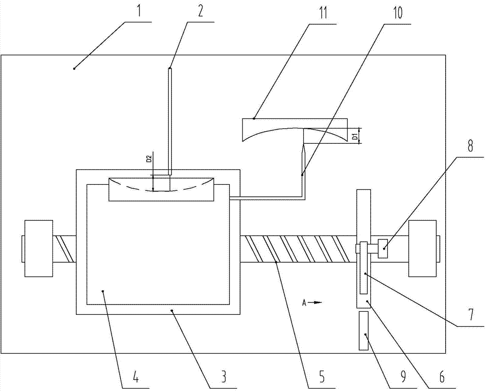
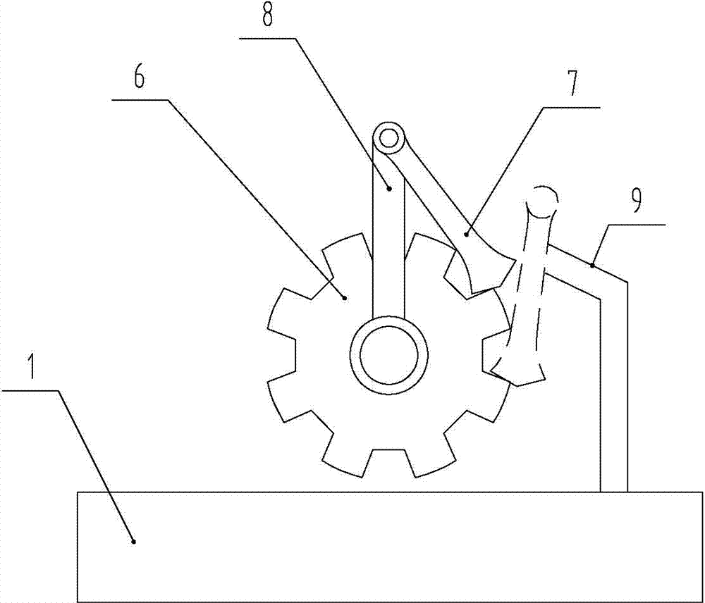
[0013] The present invention will be described in detail below with reference to the accompanying drawings, as shown in the figure: The comb-opening machine of this embodiment includes a frame 1, a rotating cutting wheel 2, a working table 3, and a pallet 4 on the working table 3. The working table 3 is driven by the ball screw nut pair 5 to move along the axis parallel to the cutting wheel 2. The pallet frame 4 is slidingly fitted with the working table 3 and clamps the comb relative to the cutting wheel to cut teeth. The ball screw sleeve In the ratchet wheel 6, the ratchet wheel 6 is rotated by the ratchet pawl 7 which is driven by the rocker 8. The top of the ratchet pawl 7 is hinged with the rocker 8 and the pawl 7 can rotate around the hinge point to rotate the rocker 8 Both sides drive the ratchet wheel 6 to rotate in both directions, the pawl 7 drives the ratchet wheel to rotate intermittently, and the rocker 8 drives the worktable to the initial position. The pallet fra...


PUM


Abstract

The invention discloses a comb gulleting machine which comprises a rotary cutting wheel, a workbench and a plate supporting frame arranged on the workbench. The workbench is driven by a ball screw nut pair to move in the direction parallel to the axis of the cutting wheel, and the plate supporting frame is in sliding fit with the workbench and clamps a comb to move horizontally relative to the cutting wheel for carrying out teeth cutting. A screw is sleeved with a ratchet wheel and rotates along with the ratchet wheel which is stirred by a pawl, and the pawl is driven by a rocker. The top of the pawl is hinged to the rocker, and the pawl rotates on the two sides of the rocker around the hinged point to drive the ratchet wheel to rotate in two directions. The plate supporting frame clamps the comb to move relative to the rotary cutting wheel in the direction of the teeth depth, the pawl drives the workbench to enable the comb to alternately move in the length direction of the workbench, and all teeth of the comb are formed. The pawl rotates around the hinged point between the pawl and the rocker to the other side of the rocker, and drives the ratchet wheel to rotate reversely to enable the workbench to move back to the initial position. The comb gulleting machine is simple in structure and high in machining precision.

Description

technical field [0001] The invention relates to a comb gear cutting machine. Background technique [0002] The tooth cutting process of the existing comb adopts a rotary cutting wheel to cut the tooth shape. During processing, the saw wheel is fixed axially and radially, and the comb is manually clamped or controlled by a machine to move along the length direction of the comb and the tooth depth direction relative to the rotary cutting wheel. Manual clamping is used, and the machining accuracy is low; because the comb has many teeth, the distance between the teeth is close, and the machine control is used, which requires frequent starting and braking, the machine wears quickly, and the processing cost is high. [0003] Therefore, aiming at the deficiencies in the prior art, it is necessary to develop a comb gear opening machine with simple structure and high machining accuracy. Contents of the invention [0004] In view of this, the technical problem to be solved by the p...

Claims


Application Information

Patent Timeline
IPC IPC(8): B23D33/02B23D33/06B26D5/20
Inventor 陈基禄
Owner WUXI COUNTY FARUI WOODEN PRODS PROFESSIONAL COOPERATION
Why Eureka
Try Eureka