Combined subsonic air intake device of aircraft

A technology for air intake devices and aircraft, which is applied in the direction of combustion at the intake port of a power plant, and can solve the problem of poor flow field distortion at the outlet of the buried air intake, low recovery coefficient of the total pressure of the buried air intake, and Problems such as large distortion of the flow field at the outlet of the airway, to achieve the effect of ensuring long-range flight capabilities, RCS stealth penetration capabilities, and good airflow distortion

Active Publication Date: 2014-02-19
JIANGXI HONGDU AVIATION IND GRP
View PDF5 Cites 15 Cited by
  • Summary
  • Abstract
  • Description
  • Claims
  • Application Information

AI Technical Summary

Problems solved by technology

[0006] However, it is difficult for the buried air intake to take advantage of the speed ramming effect of the airflow, so the total pressure recovery capability of the air intake is low, and the total pressure recovery coefficient σ at the outlet of the air intake is about 0.92; at the same time, the outlet of the buried air intake The flow field distortion of the engine is also poor, which has a great impact on the engine's potential and stable work
[0007] Some long-range, radar-stealth aircraft flying at high subsonic speeds need to use buried air inlets to ensure the stealth performance of the entire fuselage RCS when the aircraft approaches the target. Stealth performance requirements are not high, but the total pressure recovery coefficient σ of the buried air inlet is low, and the flow field distortion at the outlet of the air inlet is relatively large, which will have a great impact on the flight range of the aircraft

Method used


Image

  • Combined subsonic air intake device of aircraft
  • Combined subsonic air intake device of aircraft
  • Combined subsonic air intake device of aircraft

Examples


Embodiment Construction

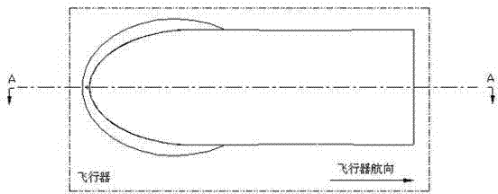
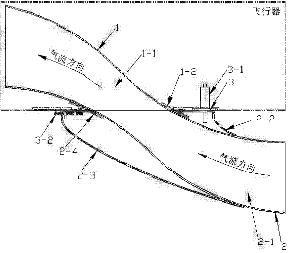
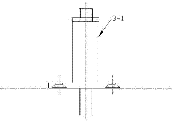
[0031] as attached figure 1 , attached figure 2 And attached image 3 As shown, the aircraft combined subsonic air intake device 1 includes a buried air intake 1, an external air intake structure 2, and an automatically separable connection mechanism 3, and the embedded air intake 1 includes a fixed air intake channel 1- 1 and fixed flange 1-2, external air intake structure 2 includes throwable air intake channel 2-1, front fairing 2-2, rear fairing 2-3 and throwable flange 2-4, which can be automatically The separated connecting mechanism 3 includes an explosive bolt 3-1 and a connecting piece 3-2. The throwable air intake channel 2-1, the front fairing 2-2 and the rear fairing 2-3 are installed and fixed on the throwable flange 2-4 with connectors, and the fixed intake channel 1-1 is installed and fixed with connectors To the fixed flange 1-2.

[0032] The fixed flange 1-2 of the embedded air intake 1 is installed and fixed on the aircraft with connectors, and the throw...


PUM


Abstract

The invention belongs to the technical field of aircraft air intake ducts and discloses a combined subsonic air intake device of an aircraft. The device comprises an embedded air intake duct, an externally-hung air intake structure and an automatically-separated connection mechanism. The embedded air intake duct comprises a fixed air intake passage and a fixed flange plate. The externally-hung air intake structure comprises a jettisonable air intake passage, a front fairing, a rear fairing and a jettisonable flange plate. The automatically-separated connection mechanism comprises an explosive bolt and a connecting sheet. The jettisonable air intake passage, the front fairing and the rear fairing are fixed to the jettisonable flange plate through connecting pieces, the jettisonable flange plate is fixed to an inlet of the embedded air intake duct on the aircraft through the explosive bolt and the connecting sheet, and an airflow outlet of the externally-hung air intake structure is matched with an airflow inlet of the embedded air intake duct. According to the device, flow distortion is good, engine thrust loss is reduced, and the flying ability of the aircraft is guaranteed; the externally-hung air intake structure is separated from the aircraft at the tail section of the aircraft, and therefore the stealth defense penetration ability of the aircraft is guaranteed.

Description

technical field [0001] The invention belongs to the technical field of aircraft air intakes, and more specifically relates to an aircraft subsonic air intake device. Background technique [0002] The subsonic air inlet can be equipped on the aircraft whose flight speed is sub-transonic, as the air intake device of the air-breathing engine. In order to reduce the flight resistance of the aircraft, the engine is generally built-in and installed inside the aircraft. Correspondingly, the subsonic air inlet has two forms: S-shaped air inlet and buried air inlet. [0003] Early aircraft mostly used S-shaped inlets. The S-shaped inlets can use the speed of airflow to pressurize. The total pressure recovery coefficient of the inlet outlet is relatively high. Generally, the total pressure recovery coefficient σ is above 0.98. According to theoretical analysis According to the statistical results of the test, an increase in the total pressure recovery coefficient of the inlet port by...

Claims


Application Information

Patent Timeline
Patent Type & Authority Applications(China)
IPC IPC(8): B64D33/02
Inventor 唐仁杰张邦楚邹敏怀杨会林彭琛高辉张小燕
Owner JIANGXI HONGDU AVIATION IND GRP
Why Eureka
Try Eureka