
Engine airflow passage structure and fanjet

A turbofan engine and airflow channel technology, which is applied to engine components, machines/engines, mechanical equipment, etc., can solve the problems of low engine aerodynamic efficiency and large flow loss, and achieve improved inlet airflow conditions, uniform flow field, and flow field Improved effect

Active Publication Date: 2014-04-09
AECC COMML AIRCRAFT ENGINE CO LTD
View PDF6 Cites 4 Cited by
  • Summary
  • Abstract
  • Description
  • Claims
  • Application Information

AI Technical Summary

Problems solved by technology

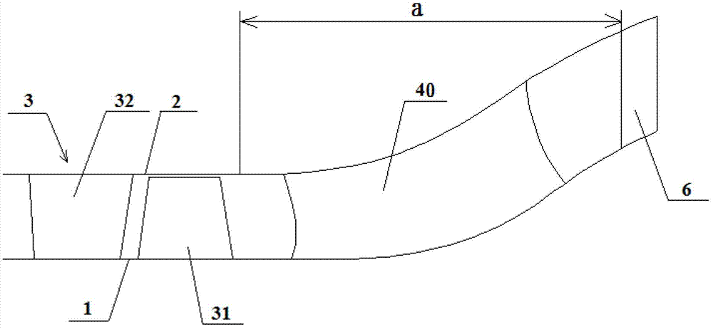
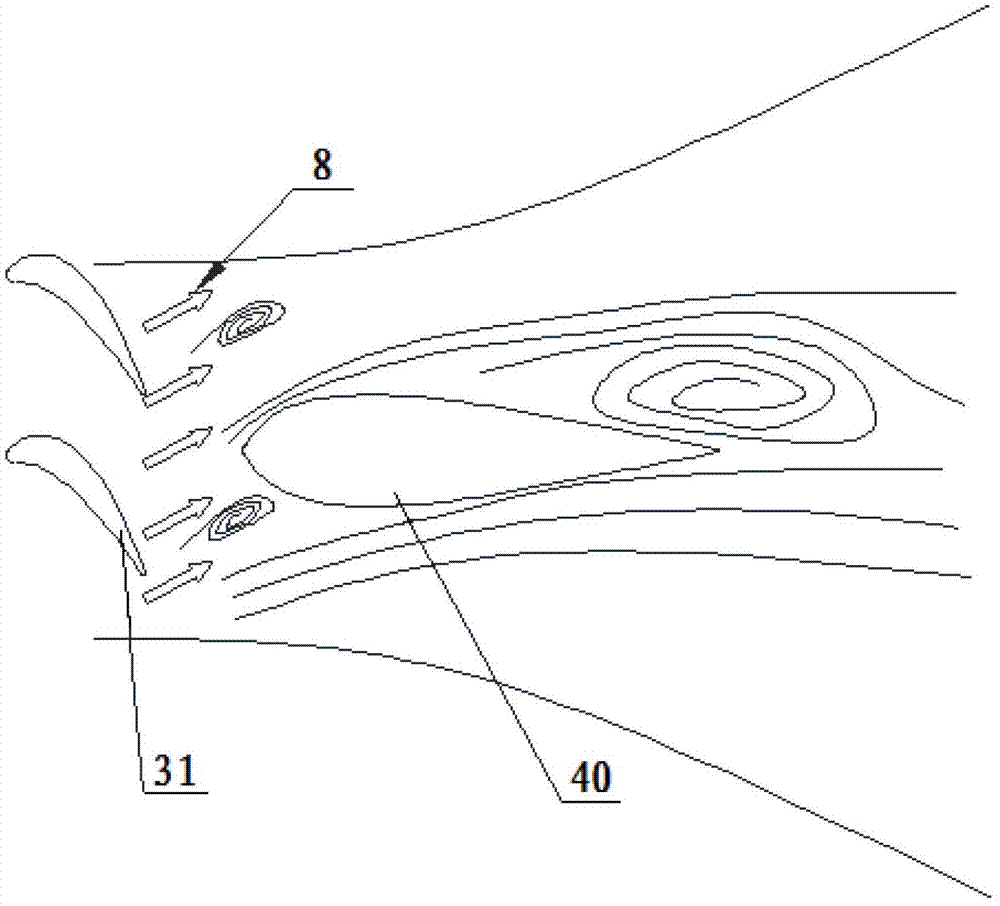
[0007] The purpose of the present invention is to propose an air flow passage structure of an engine and a turbofan engine provided with the air flow passage structure of the engine, which solves the technical problem of relatively low flow loss in the transition section in the prior art, resulting in low aerodynamic efficiency of the engine

Method used


Image

  • Engine airflow passage structure and fanjet
  • Engine airflow passage structure and fanjet
  • Engine airflow passage structure and fanjet

Examples


Embodiment Construction

[0043] Below through the accompanying drawings Figure 3 ~ Figure 5And by way of listing some optional embodiments of the present invention, the technical solution (including the preferred technical solution) of the present invention is further described in detail. It should be noted that: any technical feature and any technical solution in this embodiment are one or more of a variety of optional technical features or optional technical solutions. All the alternative technical features and alternative technical solutions of the present invention are cited, and it is not convenient for the implementation of each technical feature to emphasize that it is one of the optional multiple implementation modes, so those skilled in the art should know: Any technical features and any technical solutions in the embodiments do not limit the protection scope of the present invention, and the protection scope of the present invention should include any alternative technical solutions that th...


PUM


Abstract

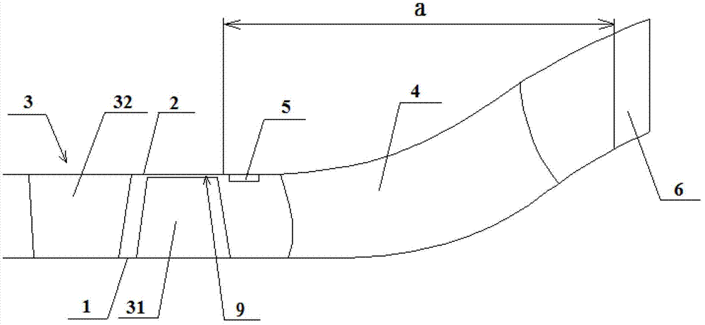
The invention discloses an engine airflow passage structure and a fanjet and relates to the technical field of aircraft engines, solving the technical problem of low erodynamic efficiency of engines due to high internal flow losses of transitional sections in the prior art. The engine airflow passage structure comprises a hub, a cartridge, turbine blades, a supporting plate and a fairing device. The turbine blades are fixedly connected with the hub, and tip clearances are reserved between tips of the turbine blades and the inner wall of the cartridge. The supporting plate is disposed between the hub and the cartridge. The fairing device is fixedly arranged on the cartridge between the turbine blades and the supporting plate, and is used for fairing airflow flowing from the tip clearances to the supporting plate and preventing the airflow from flow separation around the supporting plate. The fanjet comprises a low-pressure turbine, a high-pressure turbine and the engine airflow passage structure. With the engine airflow passage structure and the fanjet, the internal flow looses of the transitional sections can be reduced and the erodynamic efficiency of aircraft engines can be improved.

Description

technical field [0001] The invention relates to the technical field of aeroengines, in particular to an engine air flow channel structure and a turbofan engine provided with the engine air flow channel structure. Background technique [0002] For a long time to come, turbofan engines with high bypass ratios will still be the best choice for powering large airliners. The thrust generated by the fan of a turbofan engine with a large bypass ratio accounts for 60% to 80% of the total thrust of the engine. Therefore, keeping the low-pressure turbine driving the fan working at a high efficiency state is of great importance for a civil engine with a large bypass ratio. Critical. [0003] At present, the bypass ratio of civilian engines has been developed to 9~10, and the diameter of the fan exceeds 3 meters. Under such conditions, on the one hand, the high-pressure components of the engine still work at a relatively high speed (10000r / min~15000r / min), which requires the diameter ...

Claims


Application Information

Patent Timeline
Patent Type & Authority Applications(China)
IPC IPC(8): F02K3/00F01D5/12F01D9/02F01D25/24
Inventor 施鎏鎏廖坚
Owner AECC COMML AIRCRAFT ENGINE CO LTD
Learn More