Shaft body placing frame

A technology for placing racks and shafts, applied in the directions of external frames, packaging, external accessories, etc., can solve the problems of shaft damage, disordered arrangement, and inconvenient packaging trucks, so as to ensure space, avoid damage, and facilitate The effect of moving back and forth

Inactive Publication Date: 2014-02-19
ANHUI IND & TRADE VOCATIONAL TECHN COLLEGE
View PDF4 Cites 6 Cited by
  • Summary
  • Abstract
  • Description
  • Claims
  • Application Information

AI Technical Summary

Problems solved by technology

[0002] In the manufacturing plant, generally produced shafts are placed on iron frames or placed directly on the ground. It is the ground contact that can easily cause damage to the shaft body, thus affecting the normal use of the shaft body

Method used


Image

  • Shaft body placing frame
  • Shaft body placing frame

Examples


Embodiment Construction

[0017] The present invention will be further described in detail below in conjunction with the accompanying drawings and specific embodiments.

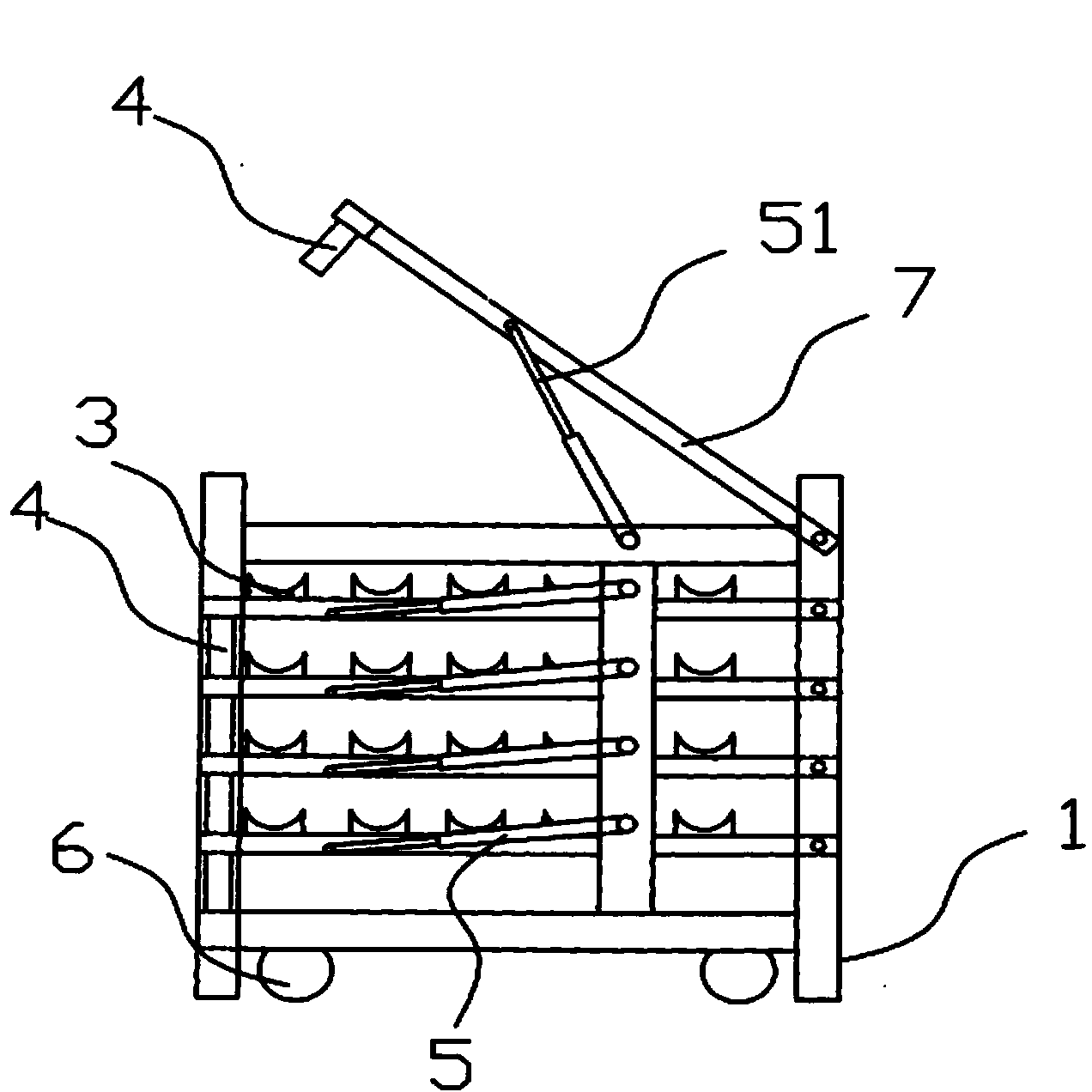
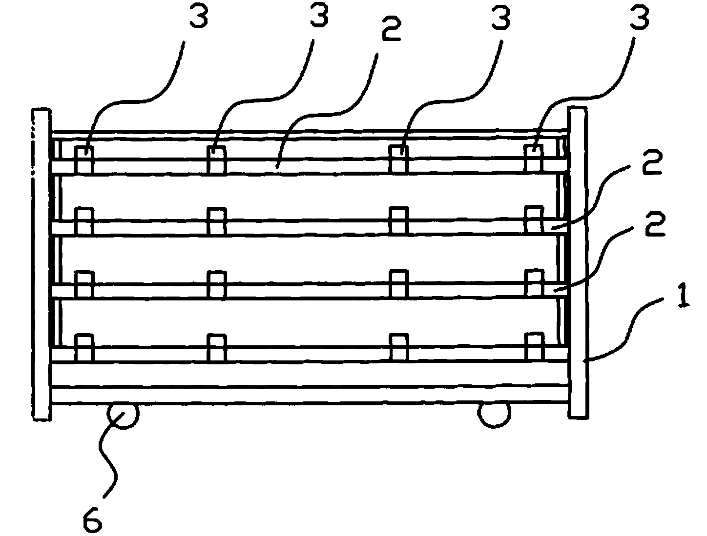
[0018] like figure 1 , figure 2 As shown, a shaft mounting frame includes a main body 1. The main body 1 is provided with several partition plates 2 in the horizontal direction. Both sides of the partition plate 2 are respectively connected with the main body 1 through adjusting rods 5 .

[0019] The top of the main body 1 is provided with a protection rod 7 , and both sides of the protection rod 7 are connected with the main body 1 through adjustment rods 51 .

[0020] The card slot 3 is made of rubber, and its shape is semicircle.

[0021] The clamping line 4 on both sides of the partition plate 2 is also made of rubber, and its bottom end faces against the upper end face of the partition plate 2 below.

[0022] The bottom of the main body 1 is provided with several pulleys 6 .

[0023] Those of ordinary skill in the art shoul...


PUM


Abstract

The invention discloses a shaft body placing frame. The shaft body placing frame comprises a body, and a plurality of partition plates are transversely arranged on the body. The shaft body placing frame is characterized in that a plurality of clamping grooves are longitudinally formed in the partition plates, clamping position lines are arranged on the two sides of each partition plate, and the two sides of each partition plate are connected with the body through adjusting rods respectively. A protective rod is arranged at the top of the body, and the two sides of the protective rod are connected with the body through adjusting rods. According to the shaft body placing frame, shaft bodies are put tidily in order, prevented from being damaged, and are convenient to move flexibly.

Description

technical field [0001] The invention relates to a layered storage frame for shaft bodies, in particular to a shaft body storage frame. Background technique [0002] In the manufacturing plant, the generally produced shafts are placed on iron frames or directly on the ground. It is the ground contact that can easily cause damage to the shaft body, thus affecting the normal use of the shaft body. Contents of the invention [0003] The technical problem to be solved by the present invention is to provide a shaft holding frame that is easy to place, has little damage to the shaft body, and can move flexibly. [0004] In order to solve the problems of the technologies described above, the technical solution adopted in the present invention is: [0005] A shaft mounting frame, comprising a main body, the main body is horizontally provided with several partition plates, characterized in that: the partition board is longitudinally provided with a group of card slots, and the two...

Claims


Application Information

Patent Timeline
Patent Type & Authority Applications(China)
IPC IPC(8): B65D61/00B65D25/20
Inventor 孔红艳
Owner ANHUI IND & TRADE VOCATIONAL TECHN COLLEGE
Why Eureka
Try Eureka