Connecting rod mechanism

A connecting rod mechanism and connecting rod technology, which is applied in the stacking of objects, unstacking of objects, transportation and packaging, etc., can solve the problems of large kinetic energy consumption, easy deviation of the stacking position of section steel, and increased production costs , to achieve the effect of reducing production cost, ensuring accurate positioning and low cost

Inactive Publication Date: 2014-02-19
JIANGYIN DADI EQUIP
View PDF4 Cites 0 Cited by
  • Summary
  • Abstract
  • Description
  • Claims
  • Application Information

AI Technical Summary

Problems solved by technology

[0002] Palletizers use magnets to transport and stack steel sections. Generally, the rails used for the flipping movement of magnets work together with multiple oil cylinders. Since there are inevitably certain errors in the strokes of

Method used


Image

  • Connecting rod mechanism

Examples


Example Embodiment

[0009] All the features disclosed in this specification, or all disclosed methods or steps in the process, except for mutually exclusive features and / or steps, can be combined in any manner.

[0010] Any feature disclosed in this specification (including any appended claims, abstract and drawings), unless specifically stated, can be replaced by other equivalent or equivalent alternative features. That is, unless otherwise stated, each feature is just one example of a series of equivalent or similar features.
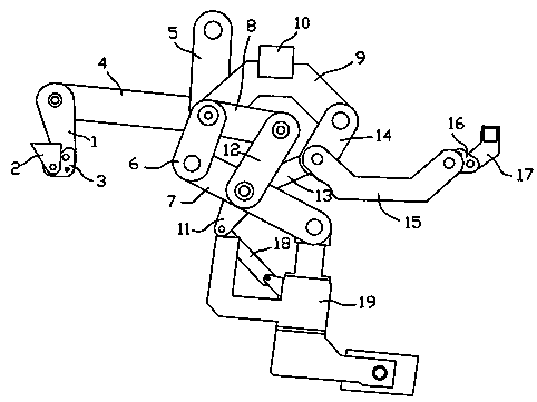
[0011] Such as figure 1 The connecting rod mechanism shown is connected by multiple connecting rods. After power is output through an oil cylinder, the connecting rods interact to realize the front and back movement of the magnet swing arm 19. The first fixed block 2, the second fixed block 10 and the third fixed block 17 are all fixed on the frame, and the first fixed block is movably connected with one end of a rotating plate 1 through a first triangular connecting plate 3...


PUM


Abstract

The invention discloses a connecting rod mechanism which comprises a plurality of connecting rods and a magnet swing arm. The connecting rods are supplied with power by an oil cylinder, and the magnet swing arm connected to the connecting rods is made to move forwards and backwards and go up and down through the mutual action among the connecting rods. Due to the fact that the length of the connecting rods is fixed, the distances of the mutual action and movement among the connecting rods are fixed, the accurate locating of the magnet swing arm can be ensued, energy resource consumption is reduced through the movement of the single oil cylinder, and production cost is reduced.

Description

technical field [0001] The invention relates to a link mechanism, in particular to a link mechanism applied to a stacker. Background technique [0002] Palletizers use magnets to transport and stack steel sections. Generally, the rails used for the flipping movement of magnets work together with multiple oil cylinders. Since there are inevitably certain errors in the strokes of the rails and cylinders, frequent adjustments are required, otherwise the stacking of section steel The position is easy to shift, and the kinetic energy consumed by this device is relatively large, which increases the production cost. Contents of the invention [0003] The invention relates to a link mechanism, which is used in a stacker to make the position of a magnet precise and reduce energy consumption. [0004] To achieve this purpose, the method adopted in the present invention is: a link mechanism, comprising a connecting rod, a fixed block and a magnet swing arm, the first fixed block is ...

Claims


Application Information

Patent Timeline
IPC IPC(8): B65G61/00
Inventor 唐瑞刚宋艳艳孙淮波
Owner JIANGYIN DADI EQUIP
Why Eureka
Try Eureka