
Cable reeling device

A winding device and cable technology, applied in transportation and packaging, delivery of filamentous materials, thin material processing, etc., can solve the problems of troublesome installation and disassembly, time-consuming and labor-consuming, and reduced production efficiency, and achieve convenient installation and disassembly, The effect of saving time for fixing screws

Inactive Publication Date: 2014-02-19
CHONGQING HENGTAI CABLE GRP
View PDF0 Cites 1 Cited by
  • Summary
  • Abstract
  • Description
  • Claims
  • Application Information

AI Technical Summary

Problems solved by technology

[0002] The roller on the cable winding device needs to be removed after the cable is fully wound. The installation and disassembly of the existing cable winding device is cumbersome, time-consuming and labor-intensive, which greatly reduces the production efficiency.

Method used


Image

  • Cable reeling device
  • Cable reeling device

Examples


Embodiment Construction

[0008] All features disclosed in this specification, or steps in all methods or processes disclosed, may be combined in any manner, except for mutually exclusive features and / or steps.

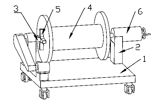
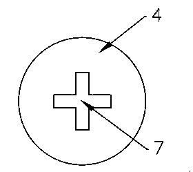
[0009] Such as figure 1 A cable winding device shown includes a base 1, a roller support 2 is installed on the base 1, a pair of roller shafts 3 are arranged on the roller support 2, and a roller shaft 3 is installed on the roller shaft 3. The cylinder 4, the roller 4 and the roller shaft are fixed by the cross fixed disk 5, the side wall of the roller 4 is provided with a groove 7 matching the cross fixed disk 5, and one end of the roller shaft 3 is installed with Regulator 6. The present invention adjusts the cross fixed disc through the adjusting device so that it can be embedded in the groove of the roller, which saves the time for fixing the screws and makes the installation and disassembly more convenient.

[0010] The present invention is not limited to the foregoing specific embodime...


PUM


Abstract

The invention discloses a cable reeling device which comprises a base. A roller support is installed on the base, and a pair of roller shafts is arranged on the roller support. Each roller shaft is provided with a roller, wherein the roller shaft and the roller are fixed through a cross-shaped fixing plate. The side wall of each roller is provided with a groove matched with the corresponding cross-shaped fixing plate, and one end of each roller shaft is provided with an adjusting device. The cross-shaped fixing plates are adjusted through the adjusting devices to be embedded into the grooves of the rollers, the time taken to fix screws is saved, and the cable reeling device can be more convenient to mount and dismount.

Description

technical field [0001] The invention relates to the field of cable equipment, in particular to a cable winding device. Background technique [0002] The roller on the cable winding device needs to be unloaded after the cable is fully wound. The installation and disassembly of the existing cable winding device is cumbersome, time-consuming and labor-intensive, and greatly reduces production efficiency. Contents of the invention [0003] The present invention provides a cable winding device for the above-mentioned deficiencies. The cylinder, the roller and the roller shaft are fixed by a cross fixed disk, the side wall of the roller is provided with a groove matching the cross fixed disk, and an adjustment device is installed at one end of the roller shaft. [0004] The beneficial effect of the present invention is that the cross fixed plate is adjusted by the adjusting device so that it is embedded in the groove of the roller, which saves the time for fixing the screws and...

Claims


Application Information

Patent Timeline
IPC IPC(8): B65H54/54
Inventor 陈志田
Owner CHONGQING HENGTAI CABLE GRP
Learn More