Lamp and liquid-cooling radiator thereof

A technology of liquid cooling and heat dissipation, lamps and lanterns, applied in the direction of cooling/heating devices of lighting devices, lighting devices, lighting and heating equipment, etc., can solve the problems of slow heat dissipation, many parts, difficult installation and disassembly, etc., to improve heat dissipation The effect of high performance, fast flow speed and easy assembly and disassembly

Inactive Publication Date: 2014-06-11
OCEANKING DONGGUAN LIGHTING TECH +2
View PDF4 Cites 23 Cited by
  • Summary
  • Abstract
  • Description
  • Claims
  • Application Information

AI Technical Summary

Problems solved by technology

In the prior art, most lamps only rely on the lamp housing to transfer heat to the lower temperature part. This way of heat dissipation is slow, and the heat cannot be transferred out in time, which may easily cause the light source, circuit board or electronic components to burn out, and this This method will cause uneven heat distribution of the lamp housing, and long-term local thermal expansion and contraction may easily lead to cracking of the lamp housing
Although some lamps are equipped with heat sinks, these heat sinks have complex structures and many parts, which are not easy to install and disassemble.

Method used


Image

  • Lamp and liquid-cooling radiator thereof
  • Lamp and liquid-cooling radiator thereof

Examples


Embodiment 1

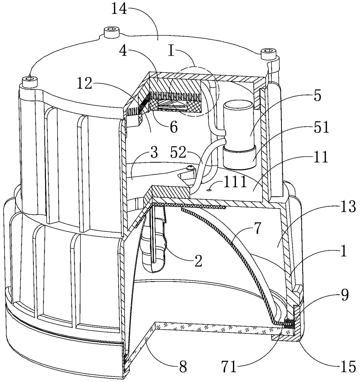
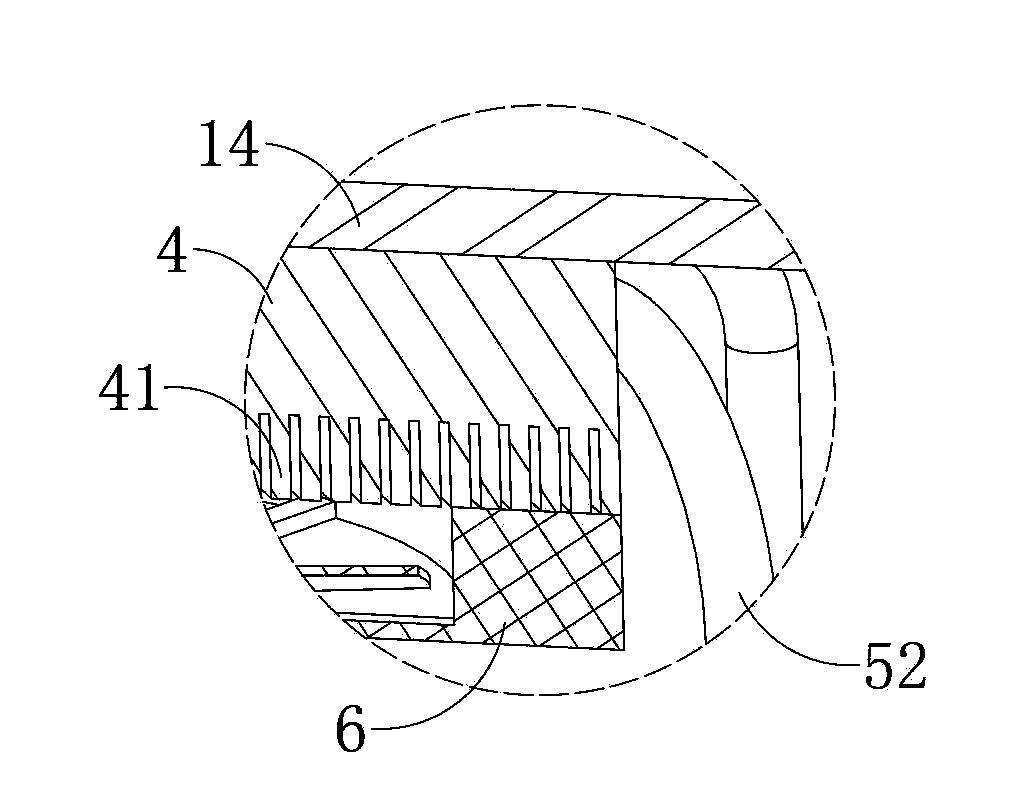
[0027] Embodiment one: see figure 1 , in this embodiment, the partition 11 is integrally formed with the lamp housing 1, the first chamber 12 forms a closed cavity by setting a rear cover 14, and the heat exchanger 4 is installed on the rear Cover 14 on. This method is suitable for the situation that the parts of the cooling device can be replaced and installed at the back of the lamp, and the parts of the cooling device can be replaced by opening the rear cover 14 . The partition 11 is formed integrally with the lamp housing 1 , and the heat on the partition 11 is more easily transferred to the lamp housing 1 , which is beneficial to the rapid dissipation of heat.

Embodiment 2

[0028] Embodiment two: see figure 1 , in this embodiment, the partition 11 is installed in the lamp housing 1 through fasteners, the tail end of the lamp housing in this embodiment is sealed without a rear cover, and the parts of the heat sink are replaced by opening the partition 11 Parts, this type of luminaire is suitable for situations where parts cannot be replaced at the rear end, for example, a luminaire embedded in a wall or placed in water at the end.

Embodiment 3

[0029] Embodiment three: see figure 1 , in this embodiment, the partition 11 is installed in the lamp housing 1 through fasteners, the first chamber 12 forms a closed cavity by setting a rear cover 14, and the heat exchanger 4 is installed on the back cover 14. This embodiment can not only replace parts of the heat sink at the tail end of the lamp housing, but also open the partition 11 to replace parts of the heat sink, which is suitable for lamps with different needs.

[0030] In the above three embodiments of the structure of the lamp housing 1 and the partition 11 , the partition 11 can also be provided with an exhaust hole 111 . The air in the first chamber 12 will absorb heat and expand, causing the pressure in the chamber to increase. If the pressure is too high, it may cause the lamp housing to be swollen and cracked. If it is not properly discharged, it will easily cause the temperature of the water pump 51 to be too high and burn out. The vent hole 111 penetrating...


PUM


Abstract

The invention provides a liquid-cooling radiator of a lamp. The liquid-cooling radiator comprises a lamp shell having an opening, a light source, a water-cooling block, a heat exchanger, a water tank, a water pump, and a water pipe. The inside of the lamp shell is divided into a closed first chamber and a second chamber having an opening, by a partition. The light source is disposed in the second chamber and fitted to the partition. The water-cooling block is disposed in the first chamber and fitted to the partition. The heat exchanger and the water tank are both fitted to the inner wall of the first chamber. The water pump is mounted on the water tank. The water pipe penetrates the water-cooling block and the heat exchanger; two ends of the water pipe are connected to the water tank. The heat exchanger is provided with radiating fins provided with a fan. The partition and the lamp shell are integrated; the first chamber is provided with a rear cover; the heat exchanger is mounted on the rear cover. The liquid-cooling radiator is high in radiating efficiency and easy to demount. The invention further provides the lamp comprising a reflector, a light-permeable plate and the radiator; the lamp is high in radiating performance; a high-power light source can be used; excessively high heat is prevented from burning out the light source or the circuit board and electronic components in the lamp.

Description

technical field [0001] The invention relates to the technical field of heat dissipation of lamps, in particular to a liquid cooling heat dissipation device for a lamp and a lamp using the heat dissipation device. Background technique [0002] Many occasions require the use of lamps equipped with high-power light sources. High-power light sources generate a lot of heat, and circuit boards and electronic components are usually installed in such lamps. The board or electronic components are burned out, so the heat dissipation capability inside the lamp is particularly important. In the prior art, most lamps only rely on the lamp housing to transfer heat to the lower temperature part. This way of heat dissipation is slow, and the heat cannot be transferred out in time, which may easily cause the light source, circuit board or electronic components to burn out, and this This method will cause uneven heat distribution of the lamp housing, and long-term local thermal expansion and...

Claims


Application Information

Patent Timeline
Patent Type & Authority Applications(China)
IPC IPC(8): F21V29/02F21V29/56F21V29/67F21V29/74F21V29/83
Inventor 周明杰刘永亮
Owner OCEANKING DONGGUAN LIGHTING TECH
Why Eureka
Try Eureka