Driving rocker base

A technology of positioning holes and installation holes, which is applied in the field of swing feet, can solve the problems of inconvenient driving and simple structure of swing feet

Inactive Publication Date: 2014-02-19
李赵和
View PDF8 Cites 0 Cited by
  • Summary
  • Abstract
  • Description
  • Claims
  • Application Information

AI Technical Summary

Problems solved by technology

However, this type of rocker has a simple structure and is inconvenient to drive.

Method used


Image

  • Driving rocker base
  • Driving rocker base

Examples


Embodiment Construction

[0016] The preferred embodiments of the present invention will be described in detail below in conjunction with the accompanying drawings, so that the advantages and features of the present invention can be more easily understood by those skilled in the art, so as to define the protection scope of the present invention more clearly.

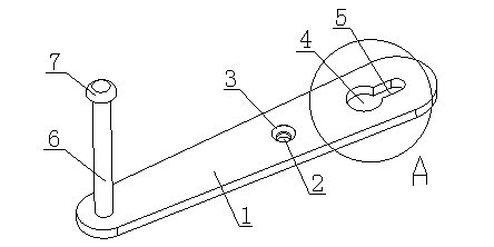
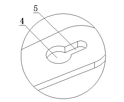
[0017] Such as Figure 1 to Figure 2 As shown, a driving rocker foot includes a rocker arm 1 made of titanium-aluminum alloy material. The middle position of the rocker arm 1 is provided with a positioning hole 3 and a connecting hole 2. The positioning hole 3 communicates with the connecting hole 2. The rocker arm 1 One end of the rocker arm 1 is provided with a mounting hole 4 and a mounting groove 5, the mounting hole 4 is circular in shape, the mounting hole 4 is connected with the mounting groove 5, the other end of the rocker arm 1 is provided with a connecting rod 6, and the end of the connecting rod 6 is provided with a buckle The cap 7 ,...


PUM


Abstract

The invention discloses a driving rocker base. The driving rocker base comprises a rocker arm made of titanium-aluminum alloy, wherein a positioning hole and a connecting hole are formed in the middle of the rocker arm; the positioning hole is communicated with the connecting hole; an installing hole and an installing groove are formed in one end of the rocker arm; the installing hole is circular; the installing hole is connected with the installing groove; a connecting rod is arranged at the other end of the rocker arm. The driving rocker base can drive a rocker conveniently, is conveniently connected with a rotating rod and is firmly connected with a pendulum rod.

Description

technical field [0001] The invention relates to a rocker foot, in particular to a driving rocker foot. Background technique [0002] In the prior art, there are some rocking feet, which often include structures such as a base, a bracket, and an arm bar. But this type of rocking foot has a simple structure and is inconvenient to drive. Contents of the invention [0003] The present invention mainly solves the technical problems existing in the prior art, thereby providing a driving rocker foot that is convenient to drive the rocker, conveniently connected to the rotating rod, and firmly connected to the swing rod. [0004] Above-mentioned technical problem of the present invention is mainly solved by following technical scheme: [0005] A driving rocker foot, including a rocker arm made of titanium-aluminum alloy material, a positioning hole and a connecting hole are provided in the middle of the rocking arm, the positioning hole and the connecting hole are connected, and...

Claims


Application Information

Patent Timeline
IPC IPC(8): F16C7/02
Inventor 李赵和
Owner 李赵和
Why Eureka
Try Eureka