Unlock instant, AI-driven research and patent intelligence for your innovation.

Universal Phase Discriminator

A phase identification, general-purpose technology, applied to the phase angle between voltage and current, instruments, phase sequence/synchronization indication and other directions, which can solve the problem of poor general performance, low phase identification accuracy, and the inability of the live display to achieve nuclear phase generalization. issues of sex

Active Publication Date: 2016-10-05
XIAMEN ANDAXING ELECTRIC GRP CO LTD
View PDF1 Cites 0 Cited by
  • Summary
  • Abstract
  • Description
  • Claims
  • Application Information

AI Technical Summary

Problems solved by technology

[0004] 1. Due to the wide variety of high-voltage live indicators on the client side, and the different voltage values ​​of the nuclear phase ports under the rated voltage, the current phase recognizers have various models and poor general performance, which is not conducive to the large-scale production of products, and the delivery time is long. High cost (custom production);
[0005] 2. The national standard must meet the phase identification function and one-side voltage loss detection function at the same time. When the nuclear phase port voltage is low, the phase recognizer that judges through the nuclear phase port voltage difference cannot meet the above requirements at the same time;
[0006] 3. The accuracy of phase recognition is low
However, the square wave shaping signal described in the patent is subjected to frequency division processing by a series of hardware circuits, the phase difference calculation is complicated, and the signal may be distorted after multi-step signal processing; at the same time, the patent only compares the phase and does not Detect the loss of voltage on one side or both sides, and the universality of nuclear phase cannot be realized for different charged displays

Method used


Image

  • Universal Phase Discriminator
  • Universal Phase Discriminator

Examples


Embodiment Construction

[0021] The present invention will be further described in conjunction with the accompanying drawings and specific embodiments.

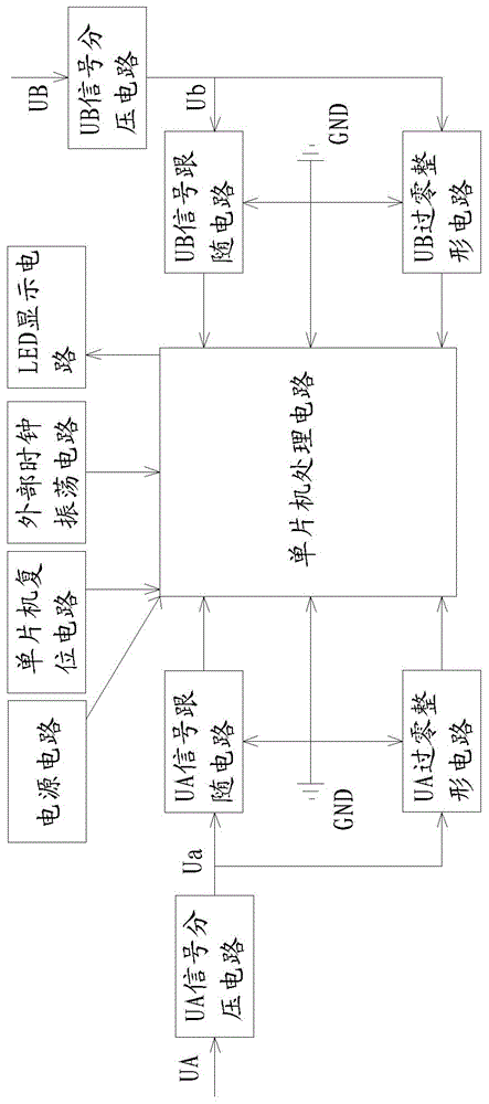
[0022] The present invention changes the realization principle of the internal circuit of the phase recognizer in the prior art, introduces a single-chip microcomputer system, adopts ADC technology, phase angle judgment, and adds a dial switch at the same time to achieve the general function of one machine with multiple functions - the same product , A full range of detection can be achieved through the setting of several DIP switches, which basically covers existing products. In addition, the ground signal is introduced to perform accurate phase verification by judging the phase angle of the two measured waveforms. At the same time, the new control circuit abandons the limitations of analog circuits (it cannot be judged at low voltage), adopts a single-chip microcomputer system, and improves the flexibility of design and the accuracy of judgment thr...


PUM


Abstract

The invention discloses a general-purpose phase discriminator, which includes UA input signal, UB input signal and GND input signal. The UA input signal passes through the UA signal voltage dividing circuit to process the large signal into a small signal Ua, and Ua respectively passes through the UA zero-crossing shaping circuit. And the UA signal follower circuit is sent to the single-chip processing circuit respectively; the UB input signal is processed into a small signal Ub through the UB signal voltage divider circuit, and Ub is respectively sent to the single-chip processing circuit through the UB zero-crossing shaping circuit and the UB signal follower circuit. The single-chip processing circuit obtains the phase angle difference between the UA input signal and the UB input signal by reading the time difference of the square wave signal obtained by the UA zero-crossing shaping circuit and the UB zero-crossing shaping circuit; the single-chip processing circuit obtains the ADC according to the UA signal following the circuit The signal and the ADC signal obtained by the UB signal follow the circuit to obtain whether one side loses voltage or both sides lose voltage; the UA signal voltage divider circuit and the UB signal voltage divider circuit are all voltage divider circuits composed of dial switches and voltage divider devices .

Description

technical field [0001] The invention relates to an electrical principle and structure used for a phase recognizer of a high-voltage electrified indicator. Background technique [0002] At present, similar products get power through the core phase ports of the two charged displays that are cored, and use voltage detection chips such as voltage comparators as key operating devices. When the voltage difference between the two core phase ports reaches the design value, the indication circuit is triggered. , the LED light is on, indicating that the phase is unbalanced, and the LED light is not on, indicating that the phase is balanced. [0003] Currently on the market, the principles of voltage indicators produced by different manufacturers are different, resulting in a large difference in the voltage amplitude of the nuclear phase port of the charged indicator under the same rated voltage. The characteristics of the voltage difference between the two nuclear phase ports as the b...

Claims


Application Information

Patent Timeline
Patent Type & Authority Patents(China)
IPC IPC(8): G01R25/00G01R29/18
Inventor 吴锦松苏秋丽李火旺
Owner XIAMEN ANDAXING ELECTRIC GRP CO LTD