RFID label antenna

A technology of RFID tags and tag antennas, applied in the field of RFID tag antennas, can solve problems such as performance limitations and performance degradation

Inactive Publication Date: 2014-02-19
ZTE INTELLIGENT IOT TECH
View PDF3 Cites 6 Cited by
  • Summary
  • Abstract
  • Description
  • Claims
  • Application Information

AI Technical Summary

Problems solved by technology

However, most RFID tag antennas in the UHF (Ultra High Frequency) band will have significant performance degradation when placed cl

Method used


Image

  • RFID label antenna
  • RFID label antenna
  • RFID label antenna

Examples


Embodiment Construction

[0022] The following will clearly and completely describe the technical solutions in the embodiments of the present invention with reference to the accompanying drawings in the embodiments of the present invention. Obviously, the described embodiments are only some, not all, embodiments of the present invention. Based on the embodiments of the present invention, all other embodiments obtained by persons of ordinary skill in the art without making creative efforts belong to the protection scope of the present invention.

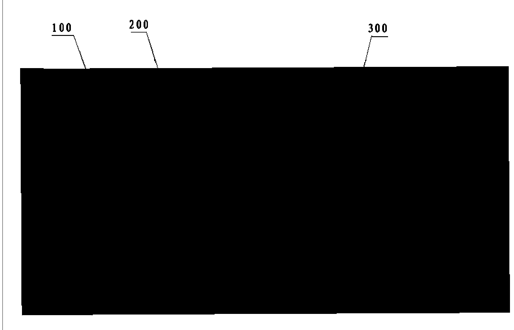
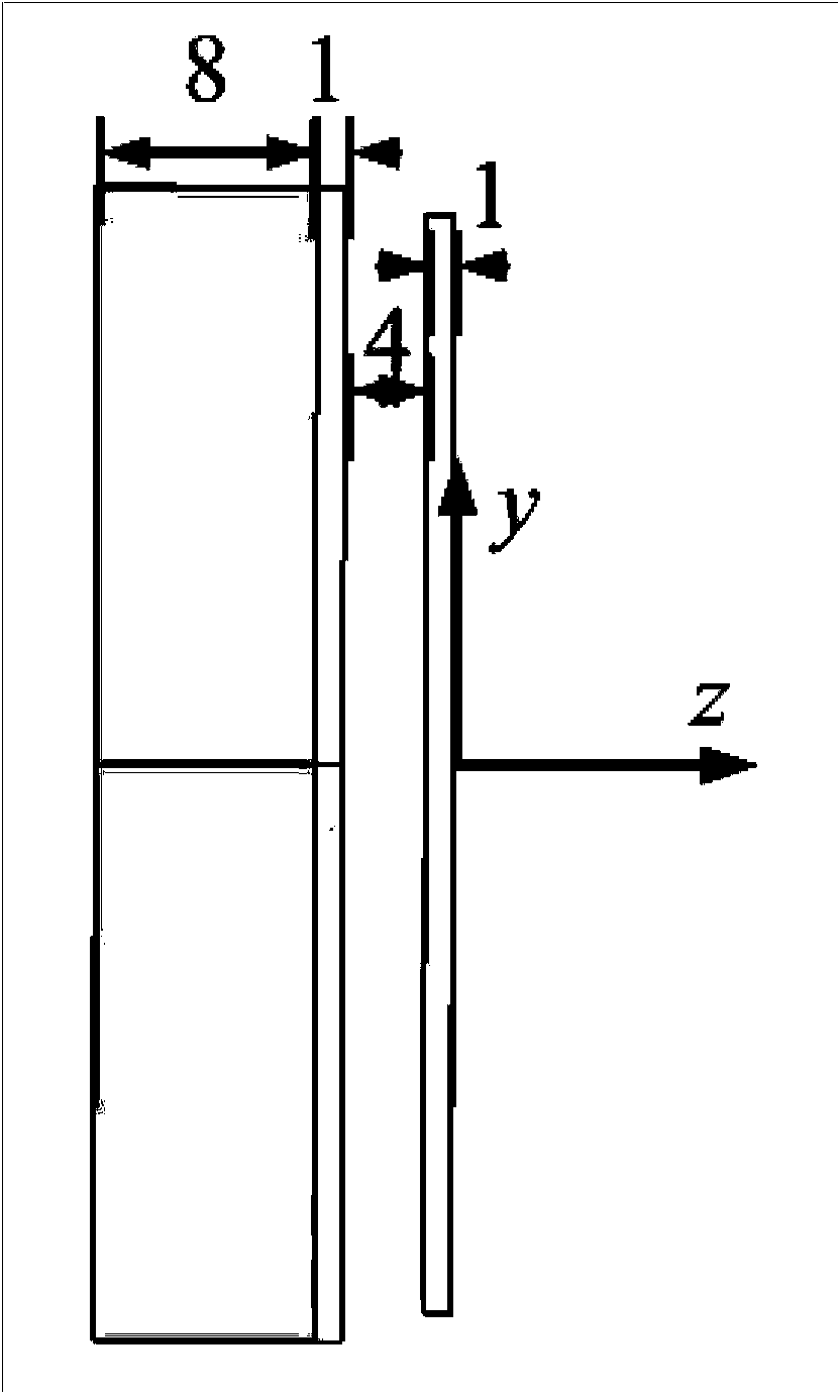
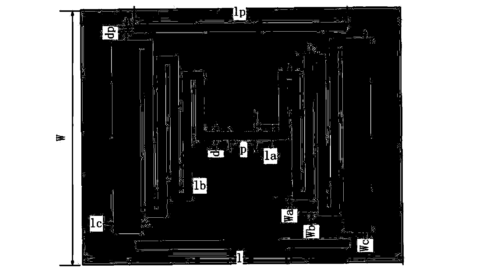
[0023] figure 1 Shown is a schematic structural diagram of the tag antenna provided by the embodiment of the present invention. Such as figure 1 As shown, the tag antenna includes: an artificial magnetic conductor (AMC) structure floor 100, an antenna substrate 200 and an antenna 300, the antenna 300 is attached above the antenna substrate 200, the antenna substrate 200 is located above the artificial magnetic conductor structure floor 100, and the structure ...


PUM

PropertyMeasurementUnit
Thicknessaaaaaaaaaa
Thicknessaaaaaaaaaa

Abstract

The embodiment of the invention provides an RFID label antenna with a metal-resisting characteristic. The RFID label antenna is characterized by comprising an artificial magnetic conductor structure floor, an antenna substrate and an antenna body, wherein the antenna body is attached above the antenna substrate, the antenna substrate is located above the artificial magnetic conductor structure floor, and a printed dipole mode is adopted for the antenna structure.

Description

technical field [0001] The invention relates to the field of radio frequency technology, in particular to an RFID tag antenna. technical background [0002] The RFID system has obvious advantages in storing product information. The product information is stored in the electronic chip of the RFID tag, which can uniquely identify the identity of the product. RFID technology has gained considerable market share and is widely used in contactless payments. Moreover, the Internet of Things system is the development direction of the Internet of Things in the future, and RFID technology is an indispensable part of the Internet of Things system. In the ideal future, every object around us can be interconnected, positioned, and processed through the Internet, and RFID Technology is the foundation of it all. [0003] In many RFID applications, in many cases, RFID tags are to be pasted on the surface of metal conductors, or close to some objects with good conductivity. Such as contai...

Claims


Application Information

Patent Timeline
IPC IPC(8): H01Q1/52H01Q1/38
Inventor 冯春楠王金龙吴群
Owner ZTE INTELLIGENT IOT TECH
Why Eureka
Try Eureka