Antenna-free radio-frequency electronic tag and design method thereof

An electronic tag and antenna-less technology, which is applied in computing, computer components, and record carriers used by machines, can solve problems such as narrow bandwidth, reduced tag reading distance, and large size, and achieve long operating distance and reading and writing distance. Far, easy processing effect

Active Publication Date: 2016-12-21
CHENGDU DESHAN TECH CO LTD
View PDF4 Cites 0 Cited by
  • Summary
  • Abstract
  • Description
  • Claims
  • Application Information

AI Technical Summary

Problems solved by technology
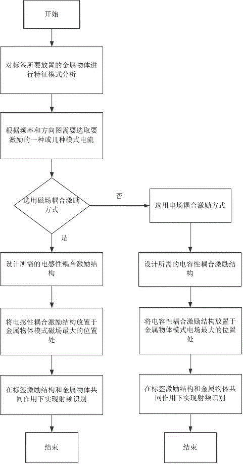
However, for ordinary passive UHF tags, when they are attached to a metal surface, due to changes in the impedance matching, distribution radiation efficiency, and directivity of the tag antenna, the reading distance of the tag decreases rapidly, and it is even difficult to be read.
Traditional anti-metal tags usually adopt the form of microstrip antennas. Although microstrip antennas have high gain, the manufacture of tag antennas is complicated, the size is large, and the bandwidth is narrow. It is difficult to achieve conjugate matching with the chip.

Method used


Image

  • Antenna-free radio-frequency electronic tag and design method thereof
  • Antenna-free radio-frequency electronic tag and design method thereof
  • Antenna-free radio-frequency electronic tag and design method thereof

Examples


Embodiment 1

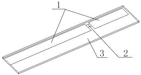
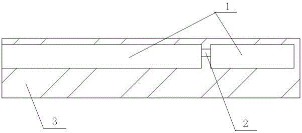
[0035] Embodiment 1 is a capacitive excitation structure such as figure 2 and image 3 As shown, it can be made of materials with higher dielectric constant and low loss. This structure is mainly used in sheet-like planar open metal structures. In this embodiment, the copper on the very thin dielectric board 1 is melted away to form a slot for placing the RFID chip 2 , and the lower end surfaces of the dielectric board 1 and the RFID chip 2 are both placed on the metal copper strip 3 . The excitation structure is placed on the edge of the metal surface where the mode current is small, and attached to the lower surface or the upper surface of the metal surface.

Embodiment 2

[0036] Embodiment 2 is an inductive excitation structure diagram, such as Figure 4 , Figure 5 and Figure 6 , which acts as a coupling coil. In this embodiment, the material 4 with high dielectric constant and low loss can be selected for processing. The metal copper strip 3 surrounds the material 4 in a circle, and the RFID chip 2 is placed at the junction of the two ends of the metal copper strip 3 . The excitation structure is placed at the place where the mode current required to be excited on the metal surface is large, and the direction of the mode magnetic field must pass through the coupling coil vertically to obtain the maximum energy coupling. At the same time, the size of the structure must be adjusted to achieve conjugate matching with the chip. This structure has certain versatility and can be used in a wide range.

Embodiment 3

[0037] Embodiment 3 is a structural diagram of embedding an inductive excitation structure into a metal object, such as Figure 7 As shown, the third excitation structure 5 adopts the structure in Embodiment 2, slots are made at the place where the eigenmode current of the rectangular metal object 6 is the largest, and the third excitation structure 5 is embedded in the metal object to excite the eigenmode current of the metal object In order to realize radio frequency identification, this structure has a certain protective effect on the label, and is concealed and beautiful.


PUM


Abstract

The invention discloses an antenna-free radio-frequency electronic tag and a design method thereof. The radio-frequency electronic tag comprises a metal object and an excitation structure, wherein the excitation structure is arranged on the surface of the metal object non-destructively or embedded in the metal object and used for exciting a radiation characteristic of the metal object; and the excitation structure is namely the electronic tag. Certain specific excitation structures are designed non-destructively and are arranged in certain specific positions of the surface of the metal object or embedded in metal and used for exciting a specific-mode current of a metal structure to realize effective radiation of the excitation structures and the metal object. The tag is simple to process, low in cost and long in operating distance; the excitation structure can be repeatedly used, so that economy and environmental protection are achieved; and the tag is hidden and attractive, and has the advantages of metal resistance, long reading / writing distance, high stability and the like.

Description

technical field [0001] The invention relates to an antennaless radio frequency electronic tag and a design method thereof. Background technique [0002] Radio Frequency Identification (RFID) is a wireless communication technology that can identify specific targets and read and write related data through radio signals without the need for mechanical or optical contact between the identification system and specific targets. According to the ISO / IEC 18000 series standards formulated by the International Organization for Standardization (ISO), the radio frequency identification technology UHF system mainly works at 902-928 MHz, the frequency bands in China are 840-845 MHz and 920-925 MHz, and the frequency bands in Europe are 865-867MHz . Passive RFID system has many advantages such as low cost, high communication rate, multi-tag identification, etc., which has attracted the attention of the industry. It is recognized as the RFID technology with the most application potential. ...

Claims


Application Information

Patent Timeline
Patent Type & Authority Applications(China)
IPC IPC(8): G06K19/077
CPCG06K19/0772
Inventor 欧阳骏梁志鹏隆锐吴贵斌鄢羿
Owner CHENGDU DESHAN TECH CO LTD
Why Eureka
Try Eureka