Reactor and power converter incorporating the reactor

a technology of power converter and reactor, which is applied in the direction of transformer/inductance cooling, inductance, electric/magnetic/electromagnetic heating, etc., can solve problems such as heat generation, and achieve the effects of excellent heat radiation properties of the reactor, efficient heat radiation, and efficient heat radiation

Active Publication Date: 2007-12-27
TOKIN CORP
View PDF7 Cites 58 Cited by
  • Summary
  • Abstract
  • Description
  • Claims
  • Application Information

AI Technical Summary

Benefits of technology

[0016]In the reactor of this power converter, the cooler is arranged being partially in contact with the core made of magnetic powder-containing resin. This may ensure a large contact area between the cooler and the reactor to achieve efficient heat radiation. That is, heat radiation of the reactor can be efficiently performed. As a result, operational stability is ensured for the reactor and electronic parts therearound, leading to the operational stability of the power converter. In this way, a converter can be provided, which has excellent heat radiation properties for the reactor.

Problems solved by technology

Thus, a supply of current to the coil may cause heat generation, and the heat is transferred to the core.

Method used


Image

  • Reactor and power converter incorporating the reactor
  • Reactor and power converter incorporating the reactor
  • Reactor and power converter incorporating the reactor

Examples


first embodiment

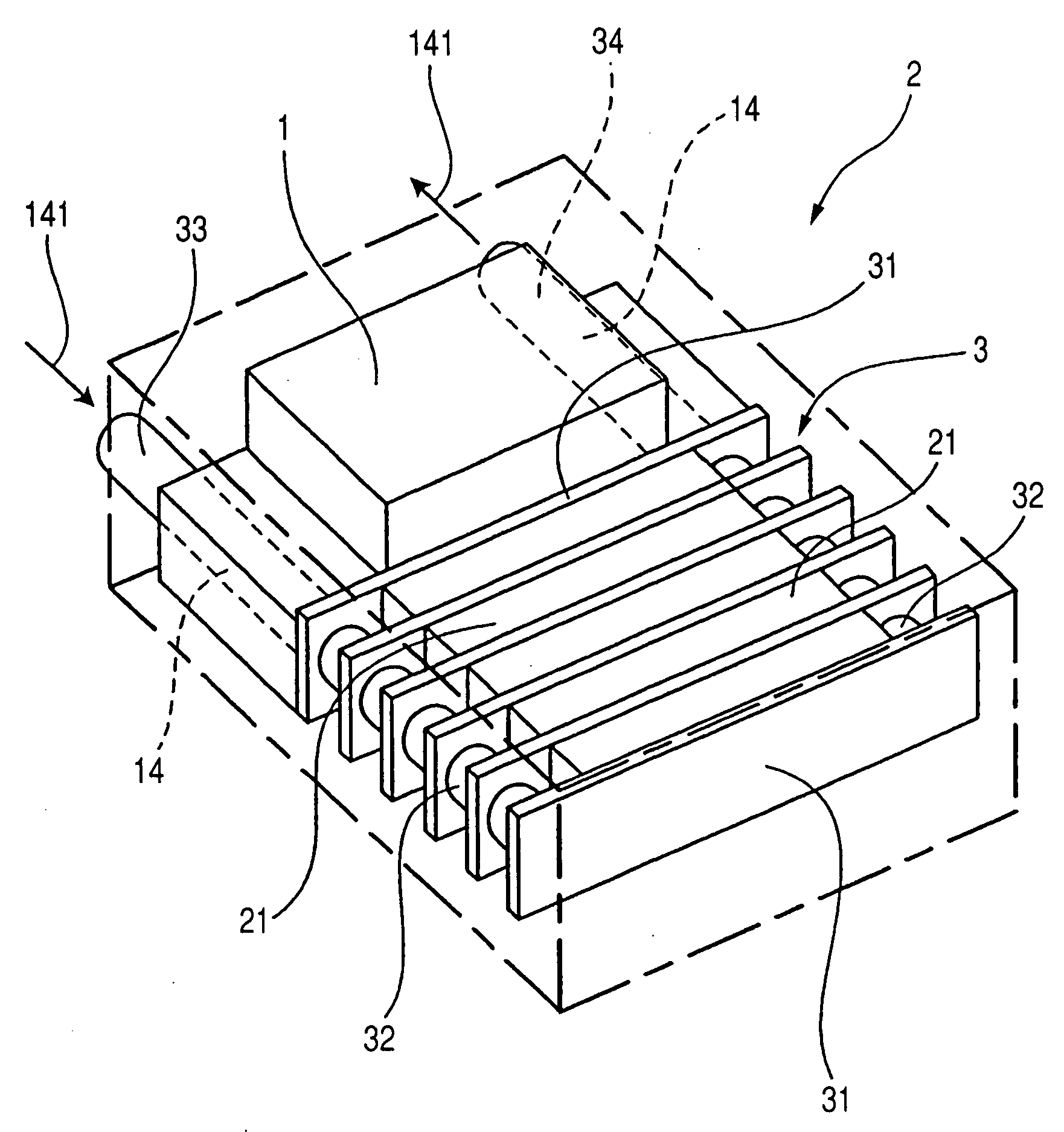
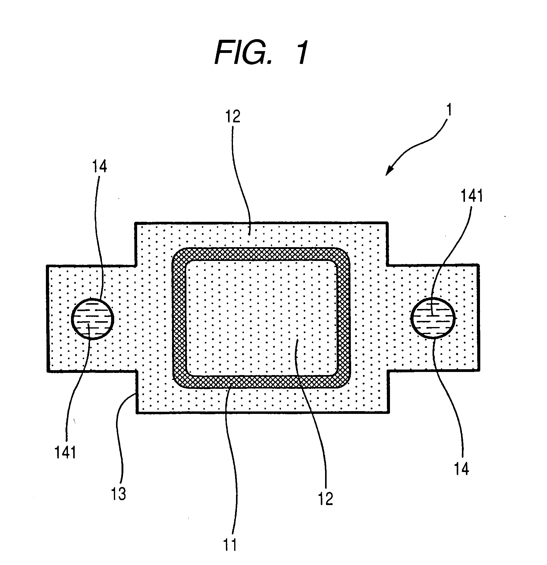
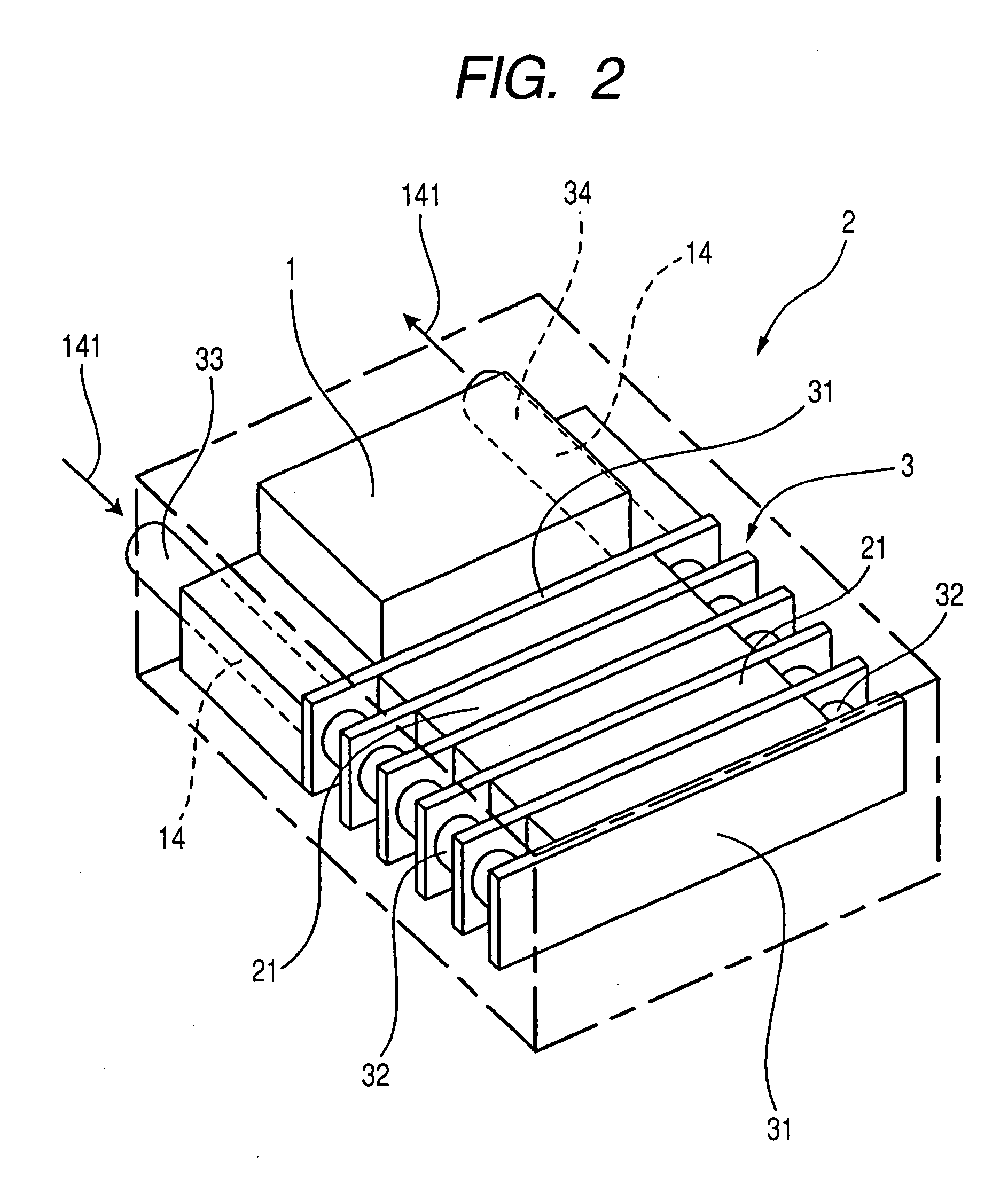
[0031]With reference to FIGS. 1 to 3, hereinafter is described a reactor and a power converter using the reactor, according to a first embodiment.

[0032]As shown in FIG. 1, a reactor 1 of the present embodiment is provided with a coil 11 that generates magnetic flux upon supply of current, a core 12 made of magnetic powder-containing resin filled in the spaces inside and outside the coil 11 so that the core 12 (i.e., the resin) comes in contact with the coil 11 directly and tightly, a case 13 accommodating therein the coil 11 and the core 12, and cooling pipes 14 as a cooling member, which are arranged being in contact with the core 12.

[0033]The cooling pipes are ensured to be embedded in the core 12 with a coolant 141 flowing therethrough.

[0034]The magnetic powder-containing resin structuring the core 12 is a material obtained by mixing a magnetic powder into a resin. The magnetic powder includes, for example, ferrite powders, iron powders and silicon alloy iron powders. The resin m...

second embodiment

[0052]A second embodiment of the present invention will now be described with reference to FIG. 4. In the present embodiment and in the subsequent embodiments, the identical or similar components to those in the first embodiment are given the same reference numerals for the sake of simplifying or omitting the explanation.

[0053]As shown in FIG. 4, the reactor 1 of the present embodiment is provided with the cooling pipes 14 which are embedded above and below the coil 11 in the core 12 in FIG. 4.

[0054]The rest of the reactor 1 is similar to the first embodiment.

[0055]Similar advantages to those of the first embodiment can be achieved in the present embodiment.

third embodiment

[0056]A fifth embodiment of the present invention is described below with reference to FIG. 5.

[0057]As shown in FIG. 5, the reactor 1 of the present embodiment is provided with the cooling pipes 14 each of which is formed into a flat shape and embedded in the core 12 outside the coil 11.

[0058]The rest of the reactor 1 is similar to the first embodiment.

[0059]In the present embodiment, heat generated from the coil 11 can be more uniformly radiated to enable so much the more efficient cooling.

[0060]In addition to the above advantage, similar advantages to those of the first embodiment can be achieved in the present embodiment.


PUM


Abstract

A reactor is provided with a coil, a core, and a case. The coil generates magnetic flux in response to supply of current thereto. The core is made of magnetic powder-containing resin filled in spaces inside and outside of the core. The case accommodates therein the coil and the core. The reactor is also provided with a cooling pipe (cooling member), which is arranged to be in contact with the core. A power converter is provided with semiconductor modules, a cooler, and the reactor. In the power converter, the cooler is arranged partially being in contact with the core of the reactor.

Description

CROSS-REFERENCE TO RELATED APPLICATION[0001]This application is based on and claims the benefit of priorities from earlier Japanese Patent Application Nos. 2006-136479 and 2006-347900 filed May 16 and Dec. 25, 2006, respectively, the descriptions of which are incorporated herein by reference.BACKGROUND OF THE INVENTION[0002]1. Technical Field of the Invention[0003]The present invention relates to a reactor provided with a heat radiating member for radiating heat generated by a coil, and to a power converter incorporating the reactor.[0004]2. Related Art[0005]A reactor is a kind of electronic parts, which is composed, for example, by winding a coil around a core made of magnetic material. Supply of current to the coil will generate magnetic flux which is distributed along the core.[0006]Operation of the reactor with the supply of current is accompanied by generation of Joule heat from the coil. This heat generation may allow the temperature of the reactor to be excessively high, whic...

Claims


Application Information

Patent Timeline
Patent Type & Authority Applications(United States)
IPC IPC(8): H05B6/12
CPCH01F27/22H01F27/40H01F2017/048H01F41/0246H01F2017/046H01F37/00
Inventor SAKA, KENJIKOSAKA, KAZUHIRONAKASAKA, AKIRA
Owner TOKIN CORP
Why Eureka
Try Eureka