Camera apparatus

a technology of camera and body, applied in the field of camera equipment, can solve the problems of large size unavoidable largeness of the whole apparatus, and similarity of the whole apparatus, and achieve the effects of reducing thickness, excellent heat transmission property, and reducing siz

Inactive Publication Date: 2006-05-11
SONY CORP
View PDF6 Cites 9 Cited by
  • Summary
  • Abstract
  • Description
  • Claims
  • Application Information

AI Technical Summary

Benefits of technology

[0029] According to the camera apparatus of the present application, since the inside structures of the camera apparatus are located within the projection surface of the disc-like recording medium loaded onto the disc rotating means, the camera apparatus can be decreased in thickness and it can be reduced in size and hence it is possible to provide a small camera apparatus which is what might be called a “disc size”.
[0030] According to the camera apparatus of the present application, since the disc compartment portion has located therein the panel which covers the mechanical deck at its portion without the arc and the panel is formed of the radiation plate with excellent heat transmission property, a clearance around the mechanical deck can be filled with the radiation plate and hence the camera apparatus can be made attractive. Further, since the spindle motor, the image pickup device and assemblies located around the spindle motor and the image pickup device can be improved in heat radiation efficiency and influence of heat can be decreased by controlling rise of temperature of the camera apparatus, devices located around the camera apparatus, assemblies and the like and hence operations of the camera apparatus can be made more reliable.
[0031] According to the camera apparatus of the present application, since the radiation plate is located close to the image pickup device or the radiation plate is brought in contact with the image pickup device, the radiation plate can radiate heat from the image pickup device so that rise of temperature of the image pickup device can be controlled. Thus, it is possible to suppress temperature from being raised by heat generated from the image pickup device and hence it is possible to prevent deterioration of image quality due to rise of temperature such as white defect occurred on the light-receiving surface of the image pickup device.
[0032] Further, according to the camera apparatus of the present application, since the sheet member having elasticity and heat transmission property is interposed between the radiation plate and the image pickup device, it is possible to protect the image pickup device by suppressing the image pickup device from being warped and deformed due to urging external force.
[0033] Furthermore, according to the camera apparatus of the present application, since the mechanical deck is located so as to divide the inside of the camera apparatus body, in which the disc rotating means and the like are accommodated, into the two chambers, the empty within the camera apparatus body can be used effectively so that the camera apparatus including the camera portion can be decreased in thickness and reduced in size.
[0034] As described above, according to the present invention, heat radiation efficiency of the image pickup device can be improved, rise of temperature of the image pickup device, the devices, the assemblies and the like located around the image pickup device can be suppressed and heat influences imposed thereon can be decreased. Thus, it is possible to realize the camera apparatus whose reliability of operation can be improved by the simple structure.

Problems solved by technology

Therefore, there is a problem in which the camera body is increased in length in the depth direction so that the whole of the apparatus becomes large in size unavoidably.
Therefore, there is a problem in which the camera body is increased in length in the lateral direction so that the whole of the apparatus becomes large in size similarly.
As described above, in the camera apparatus of this kind according to the related art, since the lens apparatus is located on substantially the same axis relative to the disc drive apparatus in an overlapping fashion and it is located distant from the disc drive apparatus with a large distance kin the lateral direction, in either case, the whole of the camera apparatus becomes large in size and hence it is not possible to make the whole of the camera apparatus small in size.

Method used


Image

  • Camera apparatus
  • Camera apparatus
  • Camera apparatus

Examples


##ventive example 1

INVENTIVE EXAMPLE 1

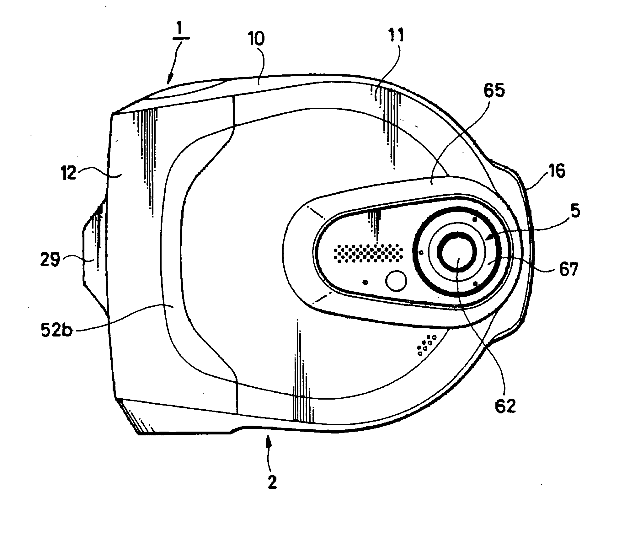
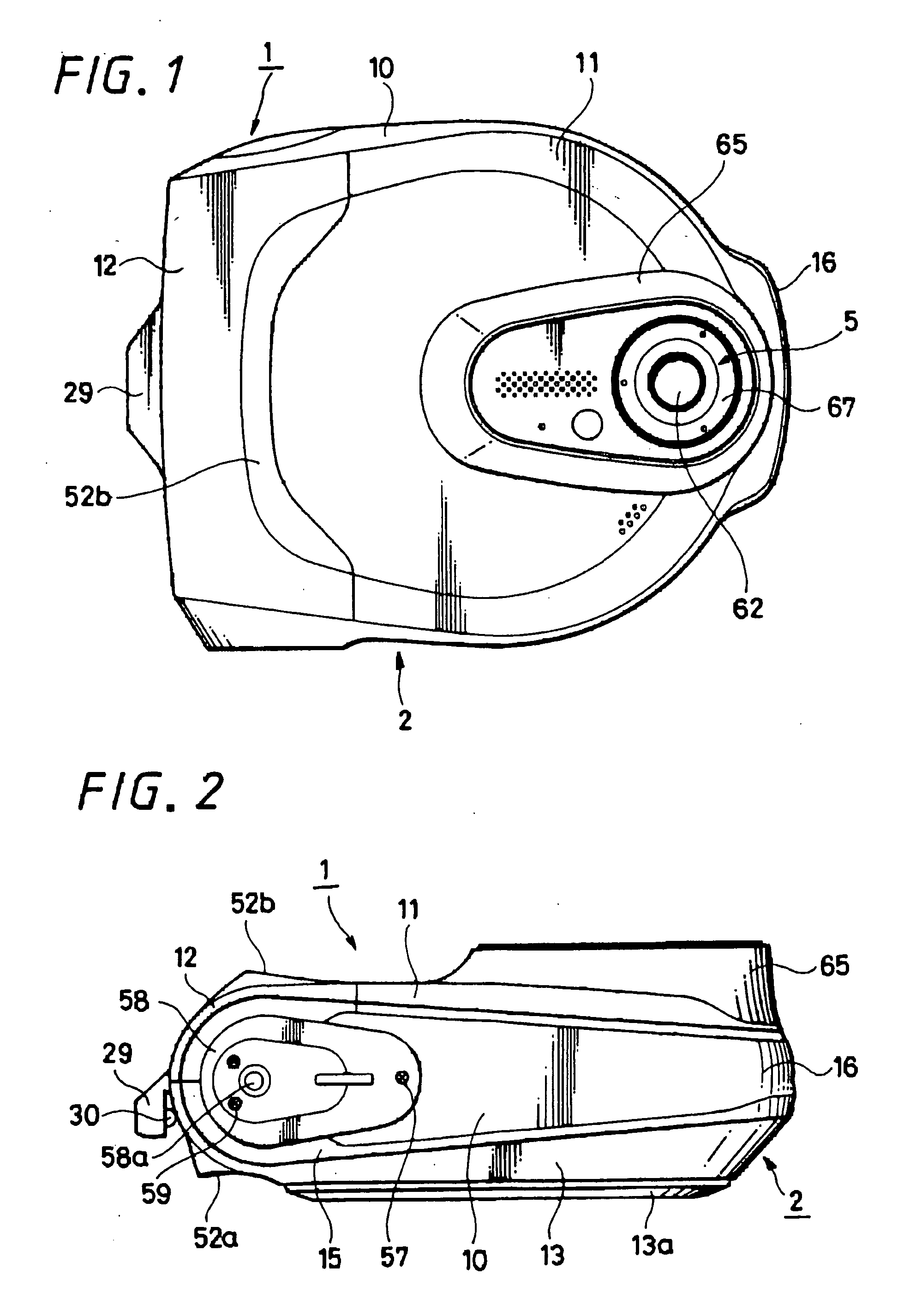
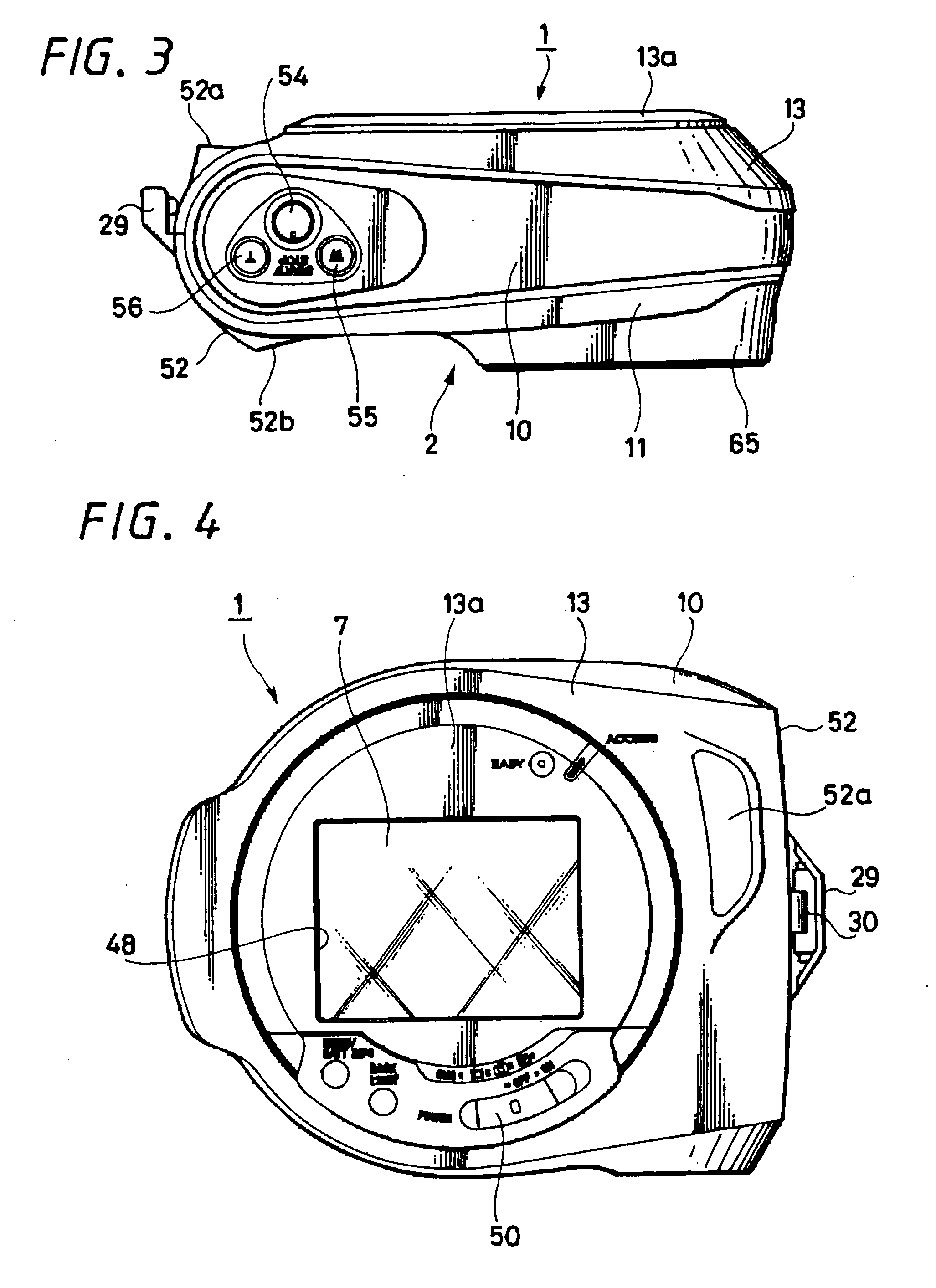
[0057] FIGS. 1 to 21 show the embodiments of the present invention. Specifically, FIGS. 1 to 7 show a disc type camera apparatus of a camera apparatus according to a first embodiment of the present invention. That is, FIG. 1 is a front view of a disc type camera apparatus; FIG. 2 is a bottom view thereof; FIG. 3 is a plan view thereof; FIG. 4 is a rear view thereof; FIG. 5 is a left-hand side elevational view thereof; FIG. 6 is a right-hand side elevational view thereof; and FIG. 7 is a perspective view of an outside appearance. FIG. 8 is a perspective view showing a disc type camera apparatus according to the present invention from the front side with its buckle being opened; FIG. 9 is a perspective view showing the disc type camera apparatus according to the present invention from the disc lid side with its disc lid and buckle both being opened; FIG. 10 is a perspective view showing the disc type camera apparatus with the disc lid being opened; FIG. 11 is an exp...

##ventive example 2

INVENTIVE EXAMPLE 2

[0123]FIG. 21 is a partly-cross-sectional perspective view showing a disc type camera apparatus according to a second embodiment of the present invention. As shown in FIG. 21, a disc type camera apparatus 301 according to this embodiment includes a camera apparatus body 302 formed of a housing extended in the front and back direction. The camera apparatus body 302 has a lens apparatus 305 provided on the upper portion of the front thereof.

[0124] A disc compartment portion 307 is set on one side surface of the camera apparatus body 302 and the disc compartment portion 307 can be opened and closed by a disc lid 303. The disc lid 303 is rotatably supported by a hinge mechanism 308 provided at the rear portion of the camera apparatus body 301, whereby the disc lid 303 can be rotated in the lateral direction at the hinge mechanism 308. Thus, the disc lid 303 is constructed as a so-called front opening type lid.

[0125] The lens apparatus 305 is composed of a combinatio...


PUM


Abstract

In this kind of related-art camera apparatus, since a lens apparatus is located on substantially the same axis of a disc drive apparatus or it is located distant from the disc drive apparatus with a large distance in the lateral direction, the whole of the camera apparatus is large in size and therefore it is not possible to make the whole of the camera apparatus compact in size. A camera apparatus includes a disc compartment portion (47) in which a DVD-R (8) is accommodated so as to be loaded and unloaded, a disc rotating apparatus (36) provided within the disc compartment portion (47) and rotating the DVD-R (8) which can be detachably loaded thereon, a lens apparatus (5) for passing light from an object, a CCD (6) for forming an image from light passed through the lens apparatus (5) and outputting an image signal corresponding to the image, an optical pickup apparatus (37) capable of recording image information on the DVD-R (8) based on the image signal outputted from the CCD (6) and a radiation plate (57) provided within the disc compartment portion (47). The radiation plate (57) and the CCD (6) are constructed so as to transmit heat therebetween so that heat can be radiated from the CCD (6) through the radiation plate (57) to the disc compartment portion (47).

Description

CROSS REFERENCES TO RELATED APPLICATIONS [0001] The present invention contains subject matter related to Japanese Patent Application JP 2004-324173 filed in the Japanese Patent Office on Nov. 8, 2004 and Japanese Patent Application JP 2004-333643 filed in the Japanese Patent Office on Nov. 17, 2004 the entire contents of which being incorporated herein by reference. BACKGROUND OF THE INVENTION [0002] 1. Field of the Invention [0003] The present invention relates to a camera apparatus using a disc-like recording medium as an information recording medium, and particularly to a camera apparatus in which a mechanical deck supporting thereon a disc rotating means is formed as substantially a D-like shape and in which a lens apparatus is located at the mechanical deck at its portion without an arc. [0004] 2. Description of the Related Art [0005] Cited Patent Reference 1, for example, has described so far a camera apparatus according to the related art. The Cited Patent Reference 1 has des...

Claims


Application Information

Patent Timeline
Patent Type & Authority Applications(United States)
IPC IPC(8): G03B17/02
CPCH04N5/2251H04N5/7605H04N23/50H04N23/54
Inventor TAKAHASHI, NOBUTATSUAMATATSU, SEIYA
Owner SONY CORP
Why Eureka
Try Eureka