Radiator with airflow guiding structure

a technology of airflow and guiding structure, which is applied in the direction of air heaters, lighting and heating apparatuses, laminated elements, etc., can solve the problems of large amount of heat often generated, weak airflow in inner sections of the channels of heat sinks, and low heat exchange efficiency between fresh air and the middle portion of the base, so as to achieve efficient heat radiation

Active Publication Date: 2005-04-21
HON HAI PRECISION IND CO LTD
View PDF14 Cites 8 Cited by
  • Summary
  • Abstract
  • Description
  • Claims
  • Application Information

AI Technical Summary

Benefits of technology

[0006] Accordingly, an object of the present invention is to provide a radiator having improved airflow path therein for efficient heat radiation.

Problems solved by technology

During operating of an electronic component such as a computer middle processing unit (CPU), a large amount of heat is often generated.
However, airflow in inner sections of the channels of the heat sink is weaker than the airflow in outer sections of the channels.
Heat exchange efficiency between fresh air and the middle portion of the base, fins adjacent the middle portion of the base is very low.
Apparently, this kind of radiator is inefficient for removing heat from the electronic component to be cooled.

Method used


Image

  • Radiator with airflow guiding structure
  • Radiator with airflow guiding structure
  • Radiator with airflow guiding structure

Examples


Embodiment Construction

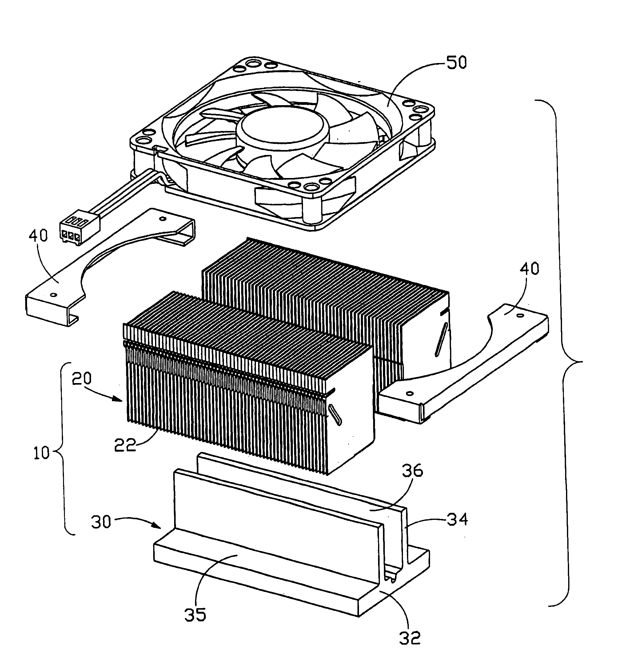
[0013] Referring to FIG. 1, a radiator in accordance with the preferred embodiment of the present invention comprises is provided to remove heat from an electronic component (not shown), such as a middle processing unit (CPU). The radiator comprises a heat sink 10 and a fan 50. The heat sink 10 comprises a heat transfer base 30 and a heat dissipation member 20 having a plurality of fins 22. The fan 50 is mounted on the heat dissipation member 20 via a pair of fan holders 40.

[0014] The heat transfer base 30 comprises a support plate 32 and a pair of separated and parallel engaging plates 34 integrally, longitudinally formed on the support plate 32. The support plate 32 has its first surface contact the CPU and forms a pair of shoulders 35 on an opposite surface. The engaging plates 34 are interposed between the shoulders 35 and respectively connectively relates with the shoulders 35. The engaging plates 34 are spaced from one another and thus define a channel 36 therebetween for rec...


PUM


Abstract

A radiator includes a heat transfer base (30), a heat dissipation member (20) secured to the heat transfer base and a fan (50) mounted to the heat dissipation member. The heat dissipation member comprises a plurality of fins (22) for dissipation heat. Air guide structures are formed between the fins for guiding air from the fan to a middle portion of the heat transfer base and a middle bottom portion of the heat dissipation member in order to enhance heat dissipating efficiency of the radiator.

Description

BACKGROUND OF THE INVENTION [0001] 1. Field of the Invention [0002] The present invention relates to radiators for removing heat from electronic components, and more particularly to a radiator having an airflow guiding structure. [0003] 2. Description of Related Art [0004] During operating of an electronic component such as a computer middle processing unit (CPU), a large amount of heat is often generated. The heat must be quickly removed from the CPU to prevent it from becoming unstable or unexpectedly. Typically, a heat sink is attached to an outer surface of the CPU to facilitate removal of heat therefrom. A fan is mounted on top of the heat sink to enhance heat dissipation efficiency. [0005] Taiwan Patent Issue No. 520152 shows a radiator having a heat sink and a fan mounted on the heat sink. The radiator comprises a flat base for contacting a surface of an electronic component, a plurality of fins extending perpendicularly from the base for radiating heat to the ambient air. Th...

Claims


Application Information

Patent Timeline
Patent Type & Authority Applications(United States)
IPC IPC(8): H01L23/467
CPCF28F3/02F28F13/06H01L23/467H01L2924/0002H01L2924/00
Inventor HWANG, CHING-BAIFANG, YI-CHYNGLIN, YEU-LIH
Owner HON HAI PRECISION IND CO LTD
Why Eureka
Try Eureka