Motor

a technology of motors and lubricating oils, applied in the field of motors, can solve the problems of increasing the temperature of the mating ring, difficult to stably ensure the supply of lubricating oil to the bearing, and difficult to effectively radiate the heat of the rotor with the mating ring, so as to improve the heat exchange efficiency of lubricating oil and increase the surface area. , the effect of increasing the surface area

Active Publication Date: 2019-11-28
TOYOTA JIDOSHA KK
View PDF5 Cites 0 Cited by
  • Summary
  • Abstract
  • Description
  • Claims
  • Application Information

AI Technical Summary

Benefits of technology

[0011]With this aspect, forming the plurality of fins on the outer peripheral surface of the mating ring along the circumferential direction ensures the increased surface area of the mating ring, thus ensuring the efficient heat radiation of the fins. Consequently, the heat exchange efficiency with the lubricating oil improves to ensure the reduced temperature rise of the mating ring, thus ensuring the reduction of the temperature rise in the driving of the motor as a result.
[0012]The present disclosure stably ensures the supply of the lubricating oil to the bearing that supports the rotary shaft of the rotor with the through hole in the mating ring and radiates the heat generated in the driving of the motor from the mating ring to the lubricating oil, thus ensuring the reduced temperature rise of the motor.

Problems solved by technology

In this case, while a heat generated in a rotor is radiated to the lubricating oil from the mating ring, it is difficult to effectively radiate the heat of the rotor with the mating ring because a surface area of the mating ring is not sufficiently ensured.
However, since a cross section of a flow passage of the lubricating oil between the outer peripheral surface of the mating ring and the motor housing decreases, it is difficult to stably ensure the supply of the lubricating oil flowing to the bearing.
Frictional heat of the mating ring and the seal ring is also applied, thus increasing temperature of the mating ring.

Method used


Image

  • Motor
  • Motor
  • Motor

Examples


Embodiment Construction

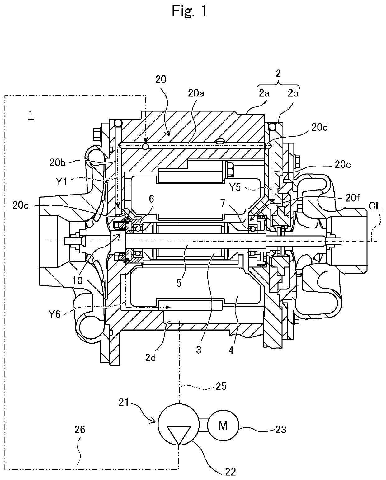
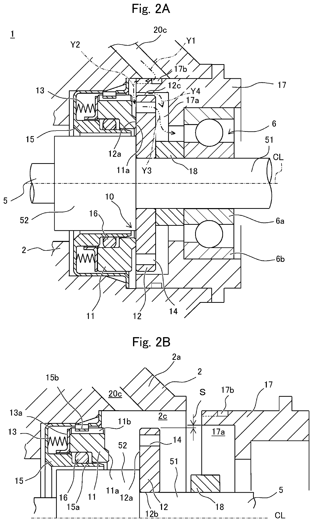
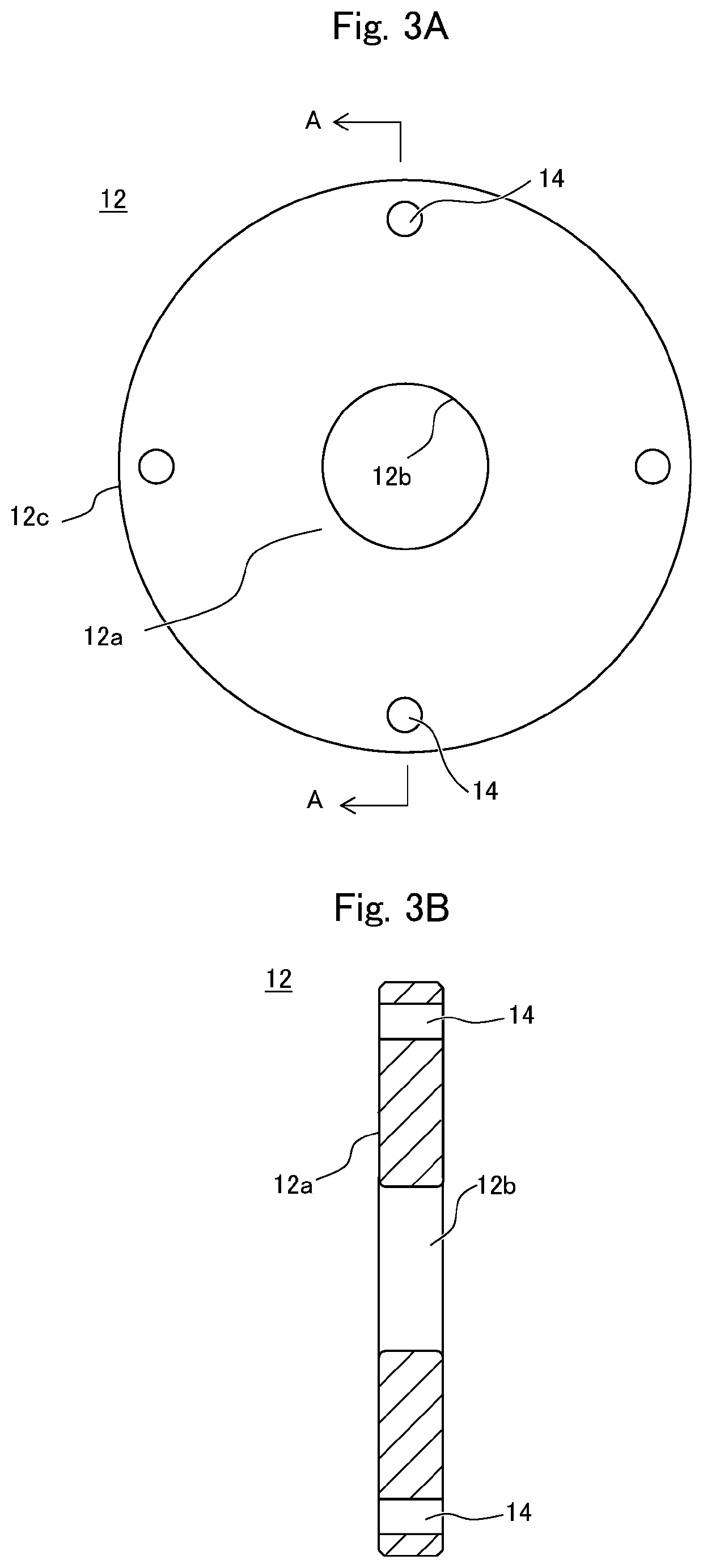
[0021]The following describes one embodiment of a motor according to embodiments of the present disclosure based on the drawings in detail. FIG. 1 is a cross-sectional view of the motor according to this embodiment. FIG. 2A is a main part cross-sectional view illustrating a mechanical seal portion of FIG. 1. FIG. 2B is a main part cross-sectional view illustrating the mechanical seal of FIG. 2A in the exploded state. FIG. 3A is a front view of a mating ring of the mechanical seal of FIG. 2A. FIG. 3B is a cross-sectional view of the mating ring taken along the line A-A of FIG. 3A viewed in the arrow direction.

[0022]A motor 1 of this embodiment includes a rotor 3 and a stator 4 in a motor housing 2. The motor housing 2 constitutes a chassis of the motor 1 and houses the rotor 3 and the stator 4. The motor housing 2 includes a main body portion 2a that houses the rotor 3, the stator 4, and the like, and a lid body 2b that covers an opening of the main body portion 2a.

[0023]The rotor 3...


PUM


Abstract

A motor that ensures efficient supply of a lubricating oil to a mechanical seal and a bearing to reduce temperature rise in driving of a motor is provided. The motor includes a mechanical seal through which a rotary shaft of a rotor is inserted. The mechanical seal includes a seal ring and a mating ring. The seal ring has a sealing surface. The mating ring is secured to the rotary shaft. The mating ring has a sealing surface that contacts the sealing surface of the seal ring. The mating ring has a through hole on an outer edge side of the mating ring with respect to the sealing surface of the mating ring. The lubricating oil flows through the through hole to the bearing side.

Description

CROSS REFERENCE TO RELATED APPLICATIONS[0001]The present application claims priority from Japanese patent application JP 2018-101053 filed on May 25, 2018, the content of which is hereby incorporated by reference into this application.BACKGROUNDTechnical Field[0002]The present disclosure relates to a motor that includes a mechanical seal at a proximity of a bearing that bears a rotary shaft of a rotor.Background Art[0003]Conventionally, JP 2004-72949 A discloses a motor that has a mechanical seal structure as this type of motor that includes a mechanical seal. In this motor, in a state where sealing surfaces of a mating ring and a seal ring of the mechanical seal hold lubricating oil, they are sealed, and the lubricating oil is supplied to the bearing.SUMMARY[0004]Now, in the motor that has the mechanical seal structure as disclosed in JP 2004-72949 A, a configuration where the lubricating oil is supplied to the bearing from between an outer peripheral surface of the mating ring and...

Claims


Application Information

Patent Timeline
Patent Type & Authority Applications(United States)
IPC IPC(8): F16C33/66H02K9/19H02K5/173H02K7/08
CPCH02K5/161F16C2380/28H02K5/1732F16C33/6666F16C33/667F16C33/76F16C33/6674F16C33/664F16C33/6659H02K7/083
Inventor NAKAMURA, KIYOHARU
Owner TOYOTA JIDOSHA KK
Why Eureka
Try Eureka