
Gantry system for particle therapy, therapy plan or radiation method for particle therapy with such a gantry system

a particle therapy and gantry technology, applied in radiation therapy, chemical to radiation conversion, radiation therapy, etc., can solve the problems of patient oriented relativeness, heavy gantry device for particle therapy, large size and high manufacturing cost, etc., and achieve the effect of reducing overall costs

Inactive Publication Date: 2007-03-08
SIEMENS AG
View PDF8 Cites 62 Cited by
  • Summary
  • Abstract
  • Description
  • Claims
  • Application Information

AI Technical Summary

Benefits of technology

[0012] In one embodiment of the gantry system, the system has a second beam guiding device. The second beam guiding device diverts the particle beam to the treatment location from an incidence direction that cannot be treated with the first beam guiding device. By means of a launching unit, a choice can be made in the radiation between the two beam guiding devices. In one exemplary embodiment, the gantry system combines the treatment of the patient with heavy particles from a fixed direction in space with lightweight particles (for example, protons) from the gantry incidence directions. The transportation of the patient from a gantry-based medical room to a fixed-beam medical room may be avoided. Thus, radiation of the patient is more efficient, and the additional possible gantry angles of incidence can be accounted for by various particles used. In this embodiment, the patient is first radiated with one type of particle and then radiated with another type of particle, from different incidence directions.
[0014] The gantry system of one exemplary embodiment makes it easier to adapt treatment strategies, which allows the mixture of proton treatments with heavier particle treatments. Accordingly, the medical rooms with a proton gantry combined with an integrated fixed beam are not reserved exclusively for proton treatments or heavy particle treatments.
[0018] In another exemplary embodiment, a quasi-fixed second beam guiding device is rotatable relative to the first beam guiding device. When the first beam guiding device rotates, the second beam guiding device remains unmoved relative to the patient. Accordingly, radiation via the second beam guiding device can be completed at every gantry rotation angle, because the beam-shaping components of the second beam guiding device are triggered independently of their rotation. Thus, the beam parameters remain essentially constant at all positions of the gantry. In this embodiment, the radiation is completed with a fixed beam even while the gantry is moving to a new position, which may save time and may increase precision of the radiation if the patient is not moved.

Problems solved by technology

Gantry devices for particle therapy are heavy, large in size and expensive to manufacture because of the mechanical requirements of at least the magnetic rigidity of the particle beam.
Thus, the gantry device that uses a carbon ion beam is more complex and more expensive to produce.
A disadvantage of the less-expensive fixed-beam treatment chamber is that the patient must be oriented relative to the beam, because the beam can not be oriented relative to the patient.

Method used


Image

  • Gantry system for particle therapy, therapy plan or radiation method for particle therapy with such a gantry system
  • Gantry system for particle therapy, therapy plan or radiation method for particle therapy with such a gantry system
  • Gantry system for particle therapy, therapy plan or radiation method for particle therapy with such a gantry system

Examples


Embodiment Construction

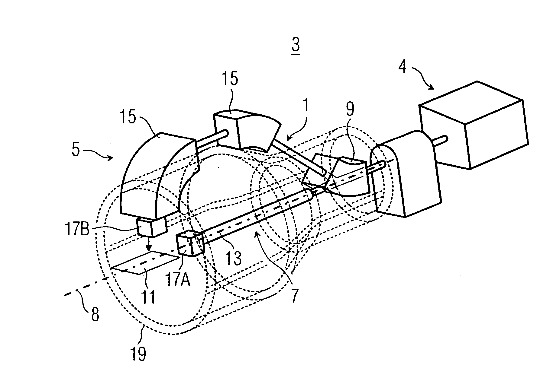
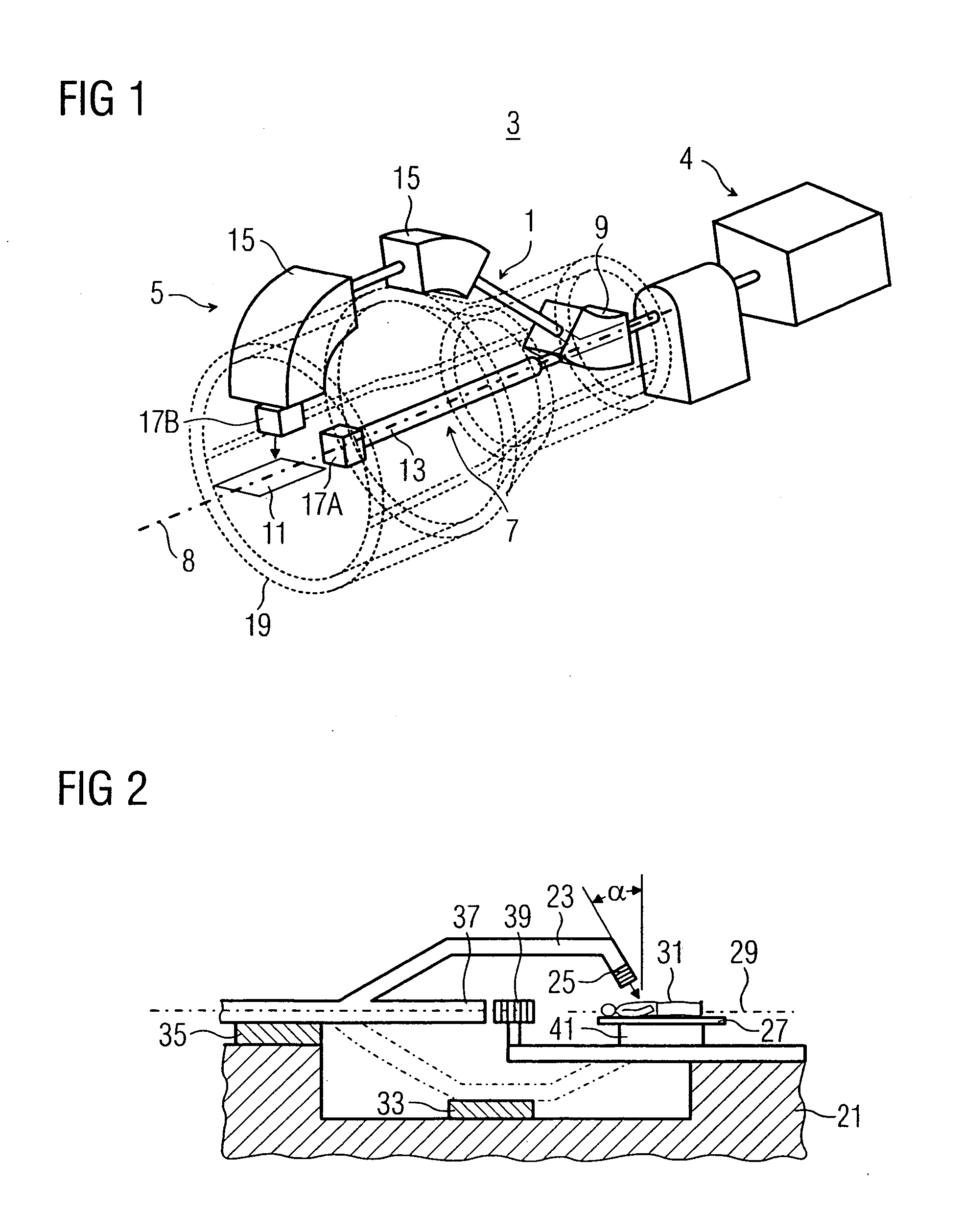
[0025]FIG. 1 schematically shows a gantry system 1. A particle beam of a particle therapy system 3 is input into the gantry system 1. The particle therapy system 3 includes an accelerator and beam delivery unit 4. The gantry system 1 includes a first beam guiding device 5 and a second beam guiding device 7. The gantry system 1 can be rotated in at least one angular range about an axis 8 of rotation. A launching unit 9 has a switch magnet coupled to and actuated by a therapy control center of the particle therapy system 3 in accordance with a treatment plan. Depending on the treatment plan entered into the particle therapy system 3, the particle beam strikes a treatment location 11 either at an angle to the axis of rotation 8 or along the axis of rotation 8. In FIG. 1, the beam path 13 of the second beam guiding device 7 extends as a central beam along the axis of rotation 8. In this exemplary embodiment, the beam path 13 is utilized as, but not limited to, a fixed beam. In an altern...


PUM


Abstract

A gantry system for particle therapy system, therapy plan and radiation method for a particle therapy with such a gantry system is provided. The gantry system for a particle therapy system includes a particle beam. A first beam guiding device rotatable about an axis of rotation of the gantry guides the particle beam so that the particle beam strikes a treatment location at a gantry incidence direction. The gantry incidence direction deviates from the axis of rotation and is variable. A second beam guiding device guides the particle beam to a treatment location in a second direction.

Description

[0001] The present patent document claims the benefit of the filing date under 35 U.S.C. § 119(e) of Provisional U.S. Patent Application Ser. No. 60 / 712,653 filed on Aug. 30, 2005, which is hereby incorporated by reference. This application also claims the benefit of DE 10 2005 041 122.3, filed Aug. 30, 2005.BACKGROUND [0002] 1. Field [0003] The present embodiments relate to a gantry system for a particle therapy system, therapy plan and radiation method for a particle therapy with such a gantry system. [0004] 2. Related Art [0005] A particle therapy system generally has a particle accelerator unit with a high-energy-beam guiding system. The acceleration of particles, such as protons, pions, helium ions, carbon ions and oxygen ions is completed with the aid of a synchrotron or cyclotron. [0006] The high-energy-beam guiding system guides the particles from the accelerator unit to at least one treatment chamber. The difference between a “fixed beam” treatment chamber and a “gantry-bas...

Claims


Application Information

Patent Timeline
Patent Type & Authority Applications(United States)
IPC IPC(8): G21G5/00A61N5/00
CPCA61N5/10A61N2005/1087A61N5/1081
Inventor KAISER, WERNERROHDJESS, HEIKOSOMMER, ANDRESUSE, TIM
Owner SIEMENS AG
Learn More