Glueless panel locking system

a panel locking and glueless technology, applied in the direction of dismountable cabinets, mechanical equipment, cabinets, etc., can solve the problems of unfavorable installation of solid flooring below ground level or directly over concrete slabs, uneven thickness of boards, so as to reduce sound transmission and moisture movement through the flooring, eliminate gaps, and simple and inexpensive construction

Inactive Publication Date: 2010-02-02
RICKER MICHAEL B
View PDF62 Cites 142 Cited by
  • Summary
  • Abstract
  • Description
  • Claims
  • Application Information

AI Technical Summary

Benefits of technology

[0018]Another object of this invention is to provide an improved panel locking system having a profile that can either be milled into the structure of each panel itself or extruded / milled from another substance and applied to a groove in the edge of the panel for versatility and reduced production expense.
[0035]Another aspect of this invention finds a locking system for the mechanical joining of at least two components of an article of construction. This system includes a first component having a first locking member, a second component having a second locking member, and at least one of the locking members being provided with a positioning member. The first locking member is located at a side edge of the first component and includes first and second flexible arm portions that are spaced apart from one another, the first arm portion including a first latching member. The second locking member is positioned along a side edge of the second component and defines a channel that is recessed within this side edge. The channel is sized to receive the arm portions without the arm portions having to contact the channel. The second locking member also includes a second latching member that is positioned and adapted to engage the first latching member. Insertion of the first locking member into the second locking member to join the first component to the second component allows the positioning member to deflect at least the first arm portion so that the first latching member becomes securely engaged with the second latching member.

Problems solved by technology

In the dry winter months, moisture leaves the wood causing the floor panels or boards to contract slightly in size, leaving unsightly gaps between each board.
In the more humid summer months, the wood expands and with too much moisture, the boards may even cup or buckle.
For this reason, solid flooring is not recommended for installation below ground level or directly over a concrete slab.
Gluing solid flooring directly to any surface including a sub-floor is not desirable because the adhesive does not allow the wood to move or breathe normally, causing the flooring to distort.
Engineered hardwood flooring, like laminate flooring, is, however, not easily repaired.
Engineered boards are more expensive than comparable solid flooring and are unavailable in the longer lengths in which solid hardwood boards are made, adding to the time and cost of installation of engineered wood floors.
This system is time-consuming and creates gaps between the boards during the heating / low humidity season.
Moreover, solid hardwood flooring is unable to utilize the interlocking technology found on engineered and laminate flooring for a number of reasons.
The ¾″ solid flooring boards are not straight enough to engage the entire edge at one time.
The present interlocking systems also create waste on both the tongue and groove sides of the board.
Milling the profile of the individual coupling elements can consume over 10% of the panel itself.
In addition, there is loss of the full face of each floor board, requiring an overlap of the boards and a reduction of the amount of usable product.
When expensive hardwood is being used, however, the financial ramifications are significant.
As explained above, solid hardwood flooring is also far less dimensionally stable than plywood or fiberboard.
Even slight dimensional changes in the profile of the interlocking structures presently found in the prior art that arise due to such factors as a change in humidity has the potential of rendering the intended system of securing one board with another entirely useless.
These systems will not work with solid hardwood flooring because the shoulders of the groove become fractured as the tongue is forced into position.
In fact, even with the high pressure laminate flooring, most of these systems where the groove is forced to open wider in order to accept the tongue have been found to fail in actual practice.

Method used


Image

  • Glueless panel locking system
  • Glueless panel locking system
  • Glueless panel locking system

Examples


Embodiment Construction

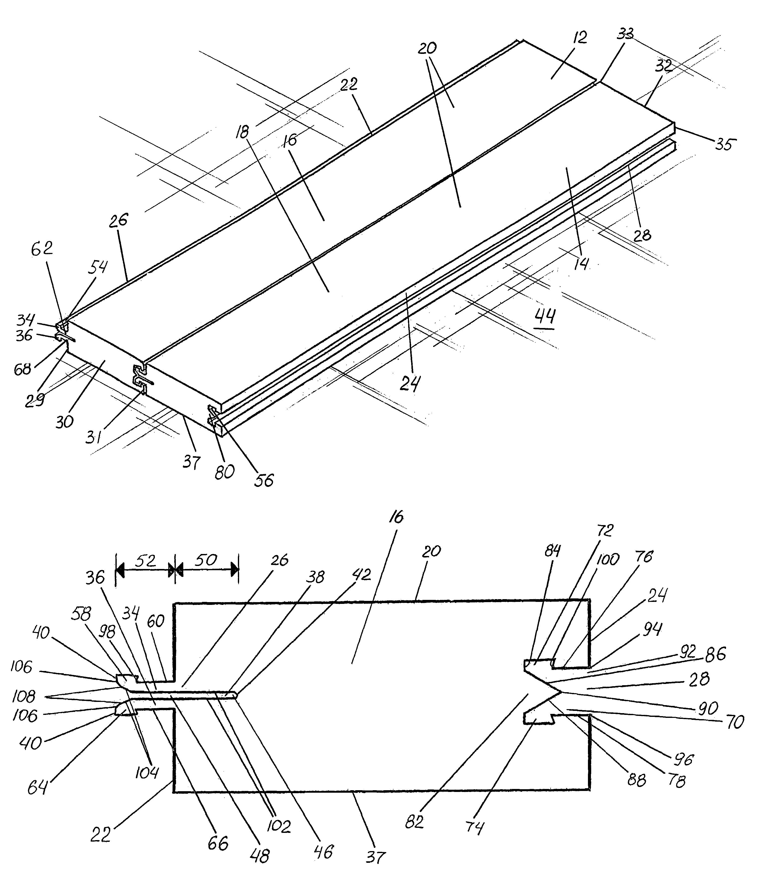
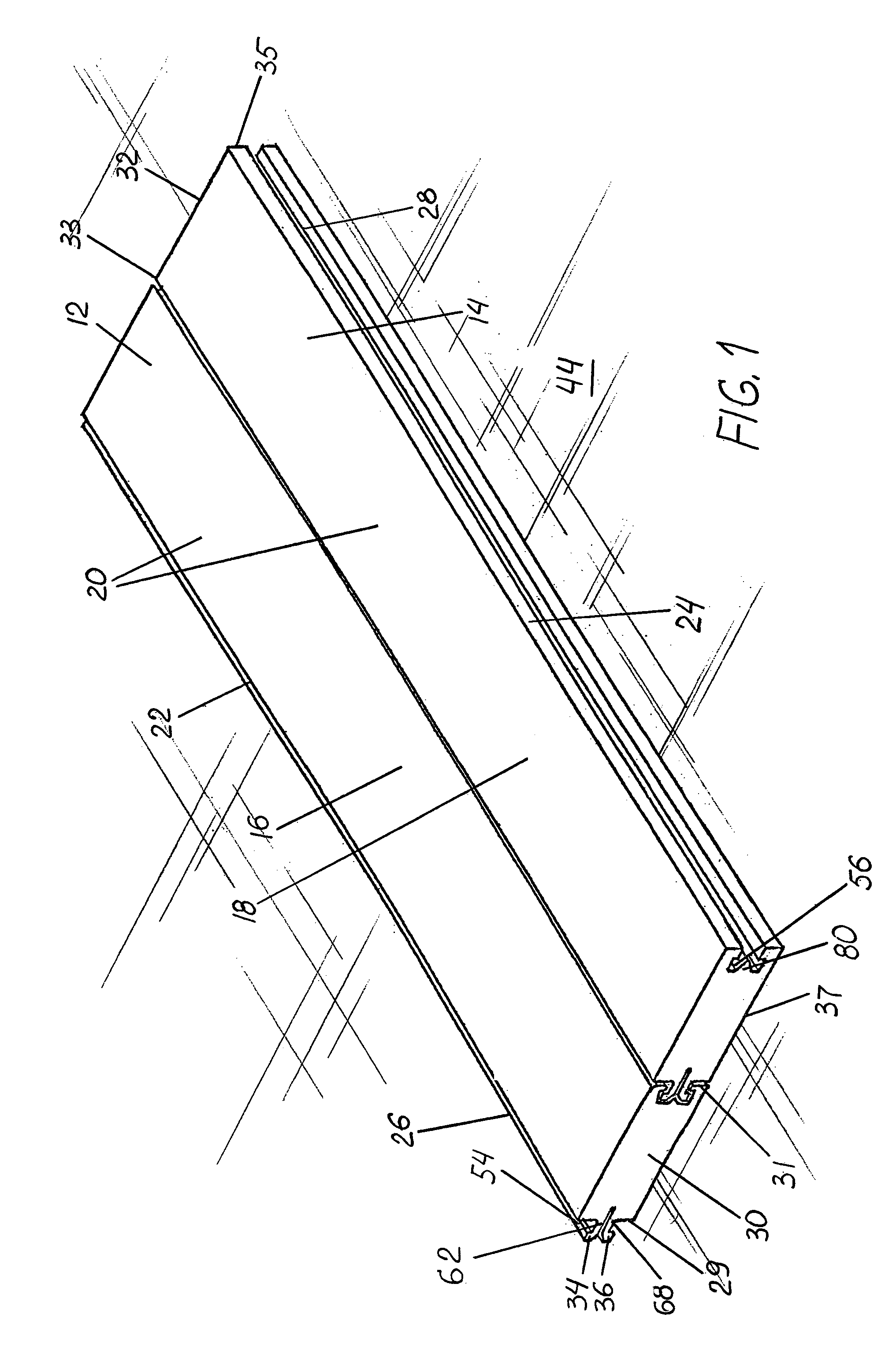
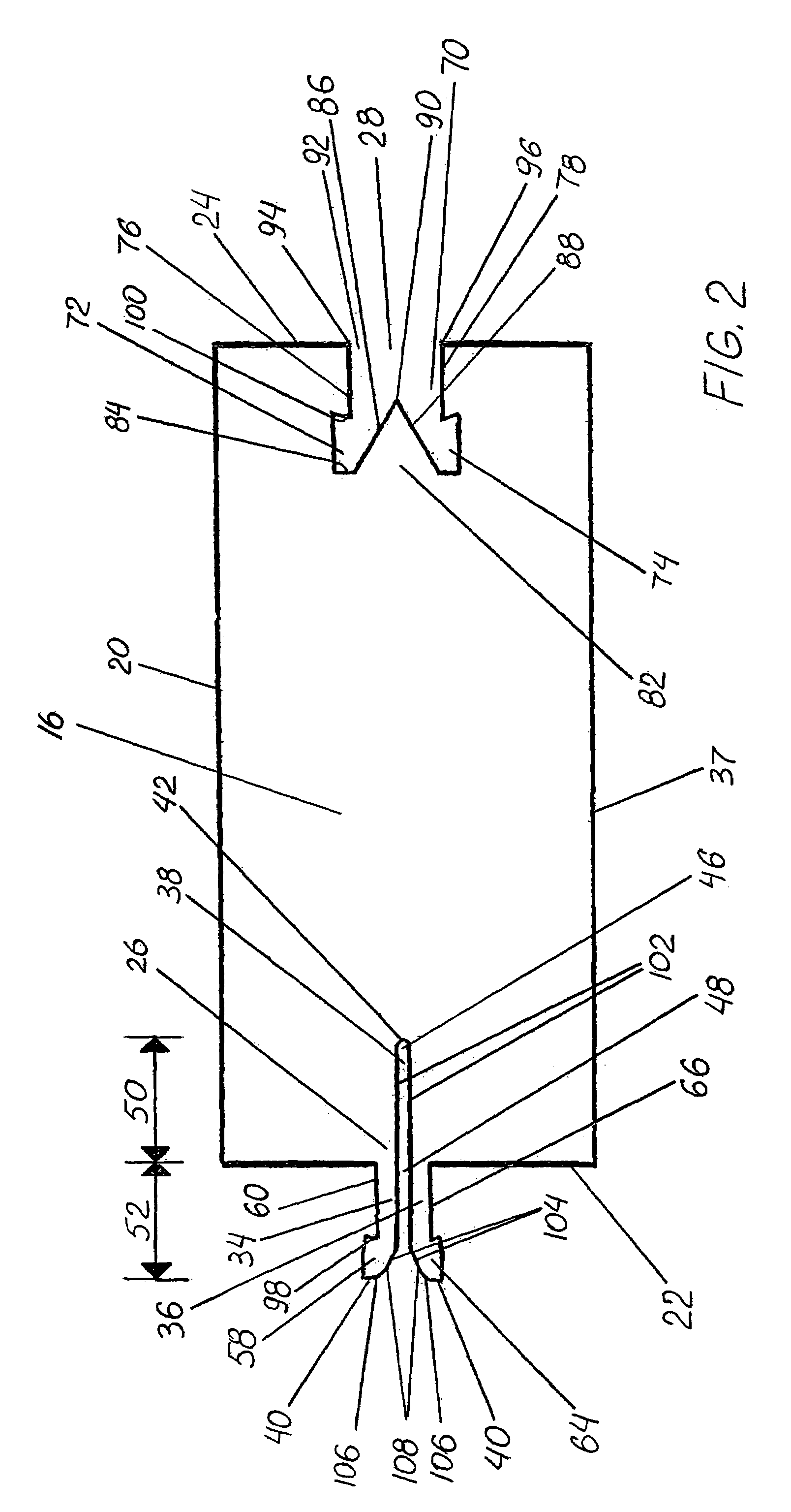
[0045]The figures illustrate preferred embodiments of an improved locking system 10 for mechanically joining together a plurality of components 12,14 to form an article of construction such as a floor or shelving. Components 12,14 are held together without utilizing an adhesive such as glue or fasteners such as nails or staples.

[0046]FIG. 1 is a perspective view of components 12,14 joined by locking system 10 where components 12,14 comprise first and second panels 16,18. Each panel 16,18 has an outer surface 20, a first side edge 22, and a second side edge 24. Panels 16, 18 are provided with first and second locking members 26,28. As shown, first locking member 26 is positioned beneath outer surface 20 extending along the length of first side edge 22 from a first end 30 of each panel to its second end 32. First end 30 extends from first-edge point 29 to second-edge point 31. Second end 32 extends from first-edge point 33 to second-edge point 35. Second locking member 28 is also posi...


PUM

PropertyMeasurementUnit
angleaaaaaaaaaa
flexibleaaaaaaaaaa
lengthaaaaaaaaaa

Abstract

A locking system for mechanically joining a plurality of panels or components of an article of construction without the need for glue or other adhesive is provided. The panels are preferably solid hardwood flooring panels. Each panel includes first and second locking members spaced beneath its outer surface. The first locking member is at one side edge of the panel and has two spaced-apart flexible arm portions, at least one arm portion including a first latching member. Preferably, the first latching member is a rib extending outward from the arm portion. The second locking member is at another side edge and includes a channel recessed within the side edge. The channel is sized to receive the arm portions without them having to contact the channel unless deflected within the channel. The second locking member also includes a second latching member positioned and adapted to engage the first latching member. The second latching member is preferably a slot abutting the channel. At least one of the locking members is provided with a positioning member so that upon inserting the first locking member on one panel into the second locking member on another panel for joining them together, the positioning member deflects an arm portion to securely engage the first latching member with the second latching member. The positioning member is preferably a wedge mounted to the back wall of the channel.

Description

FIELD OF THE INVENTION[0001]This invention is related generally to mechanical locking system for paneling and, more particularly, to mechanical locking systems for hardwood flooring not requiring the use of adhesive or other fasteners.BACKGROUND OF THE INVENTION[0002]Hardwood flooring is a $2.4 billion dollar a year industry that has been growing at a rate of more than 10% a year. Hardwood floors represent an excellent value in comparison to other flooring options since they never have to be replaced and have been shown to enhance and even increase the value of the homes in which they are installed.[0003]The current hardwood market consists of two types of products: solid and engineered. Solid flooring is generally ¾″ thick, and, as the name implies, it is made of solid hardwood. This type of product currently represents about 60% of the market or 550,000,000 square feet per year. Solid flooring includes a thick top layer that can be sanded and refinished new again several times. As...

Claims


Application Information

Patent Timeline
Patent Type & Authority Patents(United States)
IPC IPC(8): E04B5/00
CPCA47B47/0075E04F15/04E04F2201/0115E04F2201/023E04F2201/041E04F2201/05F16B5/0012
Inventor RICKER, MICHAEL B.
Owner RICKER MICHAEL B
Why Eureka
Try Eureka