
Intracardiac echocardiography image reconstruction in combination with position tracking system

an echocardiography and position tracking technology, applied in the field of medical imaging, can solve the problems of reducing the accuracy of the tool and the detector to acquire the image data, the inability to precisely locate the detector, and the major cause of mortality and morbidity, so as to reduce the time, reduce the cost, and reduce the risk of health effects

Active Publication Date: 2008-11-20
GENERAL ELECTRIC CO
View PDF99 Cites 133 Cited by
  • Summary
  • Abstract
  • Description
  • Claims
  • Application Information

AI Technical Summary

Benefits of technology

[0006]A technical effect of the embodiments of the system and method described herein includes increasing the field of view of image data acquisition employed to generate three- or four-dimensional reconstruction of images to guide an interventional surgery procedure. In general, as a surgeon moves the medical instrument with respect to the patient's anatomy, virtual images of the instrument or object are displayed simultaneously relative to real-time acquired image data represented in the model of the patient's anatomy. Another technical effect of the system and method described herein of tracking includes readily tracking the spatial relationship of the medical instruments or objects traveling through an operating space of patient. Yet, another technical effect of the system and method described herein includes reducing manpower, expense, and time to perform interventional procedures, thereby reducing health risks associated with long-term exposure of the subject to radiation.

Problems solved by technology

Yet, the sensors to the track the tool and the detectors to acquire the image data may not be precisely located due to manufacturing variation.
Heart rhythm disorders or cardiac arrhythmias are a major cause of mortality and morbidity.

Method used


Image

  • Intracardiac echocardiography image reconstruction in combination with position tracking system
  • Intracardiac echocardiography image reconstruction in combination with position tracking system
  • Intracardiac echocardiography image reconstruction in combination with position tracking system

Examples


Embodiment Construction

[0015]In the following detailed description, reference is made to the accompanying drawings that form a part hereof, and in which is shown by way of illustration specific embodiments, which may be practiced. These embodiments are described in sufficient detail to enable those skilled in the art to practice the embodiments, and it is to be understood that other embodiments may be utilized and that logical, mechanical, electrical and other changes may be made without departing from the scope of the embodiments. The following detailed description is, therefore, not to be taken in a limiting sense.

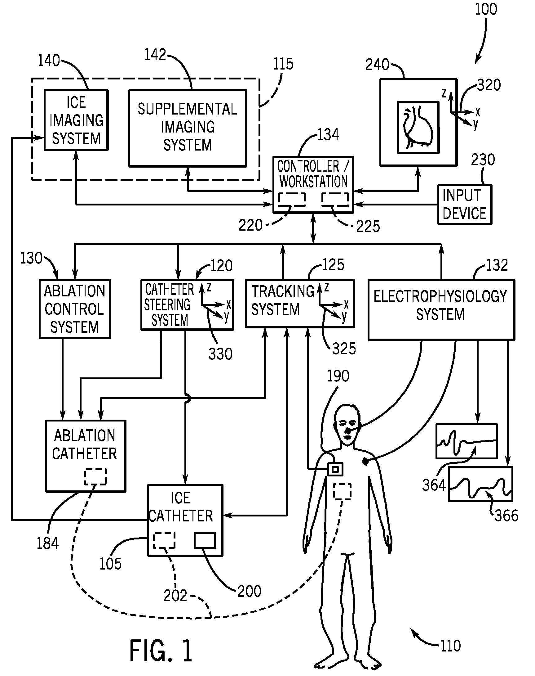
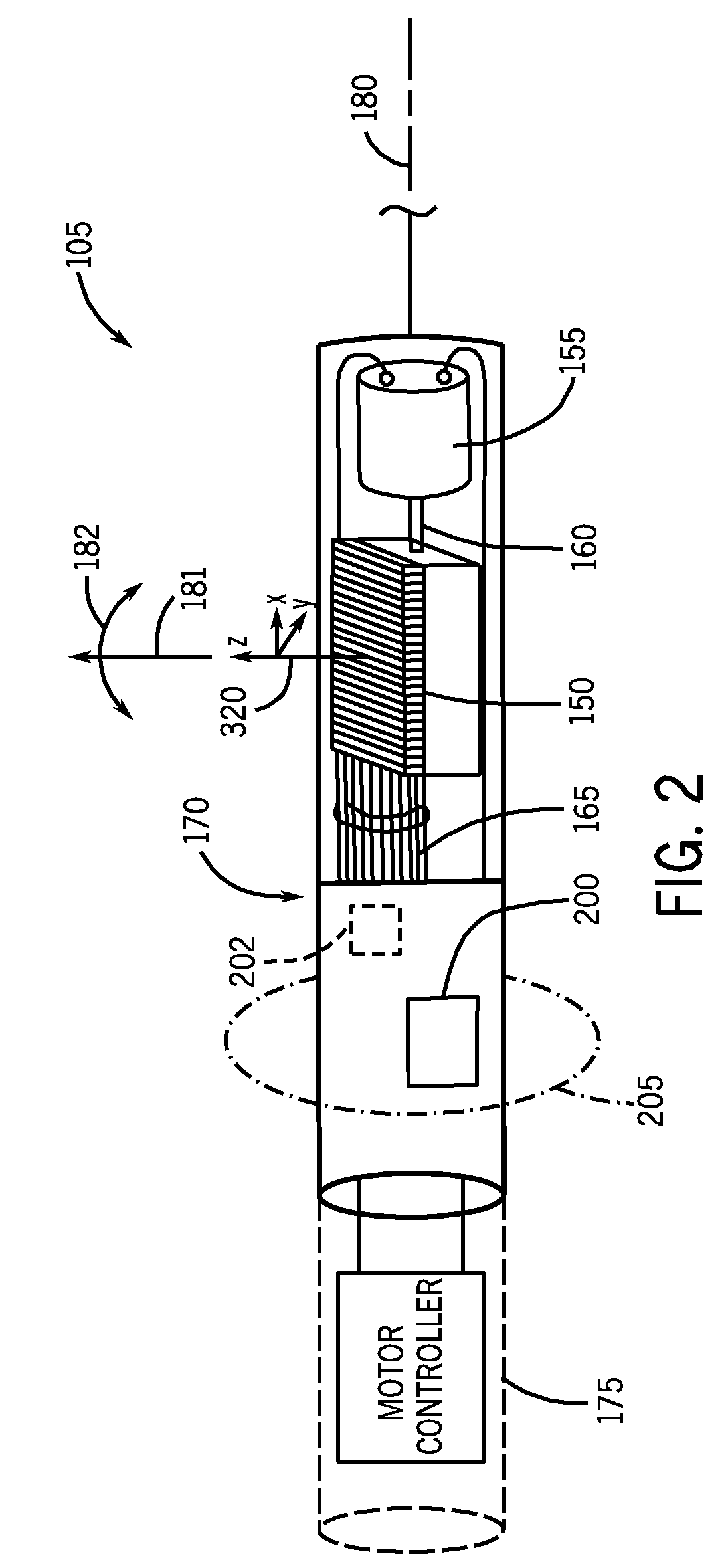
[0016]FIG. 1 generally illustrates an embodiment of a system 100 operable to create a full-view three- or four-dimensional (3D or 4D) image or model from a series of generally real-time, acquired 3D or 4D image data (e.g., ultrasound) relative to tracked position information of an imaging probe (e.g., catheter 105) traveling through the imaged subject 110. Although the following description is...


PUM


Abstract

A system and method to display a four-dimensional (4D) model of an imaged anatomy is provided. The system comprises a controller, and an imaging system including an imaging probe in communication with the controller. The imaging probe can acquire generally real-time, 3D image data relative to a direction of image acquisition along an imaging plane. The system also includes a tracking system in communication with the controller. The tracking system includes at least one tracking element integrated with the imaging probe. The system is operable to process the generally real-time, 3D image data acquired by the imaging probe relative to generally real-time tracking information acquired by the tracking system so as to display the 4D model of the imaged anatomy.

Description

RELATED APPLICATIONS[0001]This application claims priority to U.S. Provisional Application No. 60 / 938,442 filed on May 16, 2007, and is hereby incorporated herein by reference in its entirety.BACKGROUND[0002]The subject matter herein generally relates to medical imaging, and more specifically, to a system and method to navigate a tool through an imaged subject.[0003]Image-guided surgery is a developing technology that generally provides a surgeon with a virtual roadmap into a patient's anatomy. This virtual roadmap allows the surgeon to reduce the size of entry or incision into the patient, which can minimize pain and trauma to the patient and result in shorter hospital stays. Examples of image-guided procedures include laparoscopic surgery, thoracoscopic surgery, endoscopic surgery, etc. Types of medical imaging systems, for example, computerized tomography (CT), magnetic resonance imaging (MRI), positron emission tomography (PET), ultrasound (US), radiological machines, etc., can ...

Claims


Application Information

Patent Timeline
Patent Type & Authority Applications(United States)
IPC IPC(8): A61B8/00G06K9/00A61B8/14
CPCA61B5/06A61B8/445A61B6/503A61B6/541A61B8/0883A61B8/12A61B8/4254A61B8/4461A61B8/4488A61B8/483A61B8/5238A61B8/543A61B18/1492A61B19/5244A61B2017/003A61B2019/505A61B2019/5251A61B2019/5263A61B2019/5276A61B2019/5278A61B2019/5295A61B8/463A61B8/466A61B5/7285A61B8/4263A61B2034/2063A61B2090/3782A61B2090/367A61B34/20A61B2034/105A61B2034/2051A61B2090/378A61B5/062A61B5/064
Inventor LI, DUN ALEXNAFIS, CHRISTOPHER A.WILDES, DOUGLAS G.JENSEN, VERNON T.
Owner GENERAL ELECTRIC CO
Learn More