UV air cleaning & disinfecting system

a technology which is applied in the field of can solve the problems of low air throughput, low efficiency of uv units in hvac system, and relatively low amount of uv exposure of pathogens per unit volume of air processed, so as to achieve effective and efficient uv air cleaning and disinfection system, high inactivation

Inactive Publication Date: 2002-03-14
KULP JOHN C
View PDF11 Cites 60 Cited by
  • Summary
  • Abstract
  • Description
  • Claims
  • Application Information

AI Technical Summary

Benefits of technology

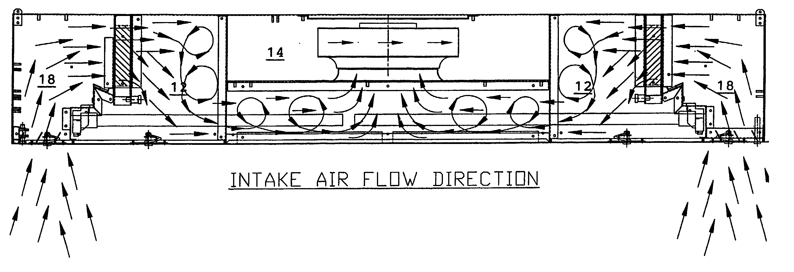
[0013] In a preferred embodiment, the UV air cleaning and disinfecting system has a main chamber with an array of UV lamps arranged longitudinally across the chassis between the inlet vents at a lower elevational position of the chassis. The inlet vents are housed in intake chambers separated from the main chamber by UV-blocking baffles directing the incoming air through air filters into the main chamber. The air blower is positioned in the center of the chassis and at an upper elevational position from the array of UV lamps. The baffles direct incoming air upwardly through the air filters then downwardly over the UV lamp array toward the center of the chassis where it is entrained by the air blower and blown latitudinally outward on opposite sides through the outlet vents in the surface panel. The upward and downward movement ofthe air causes air swirling movements which enhance the exposure of pathogens in the air on many sides thereof to ensure effective UV radiation exposure of the pathogens.
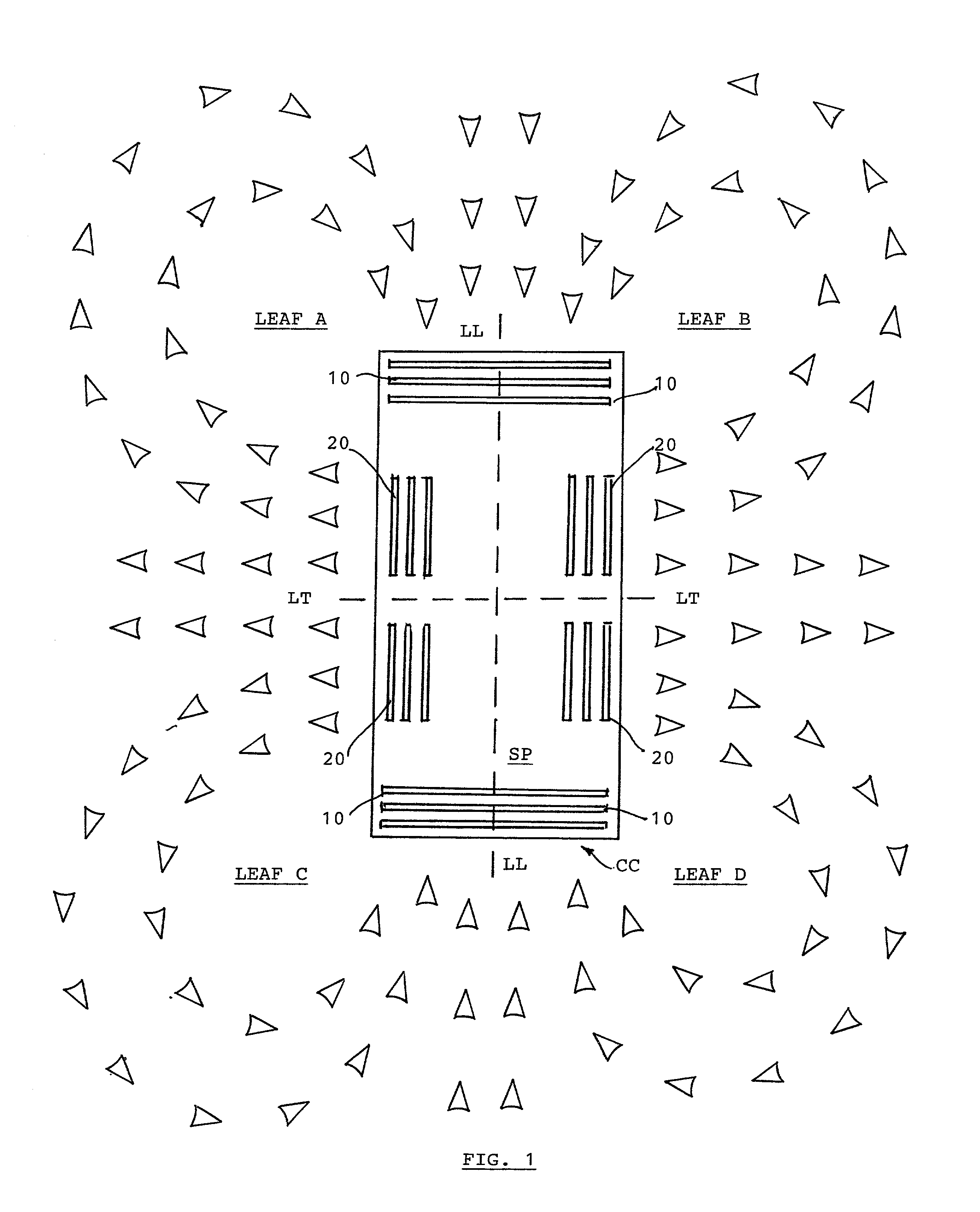
[0016] The system's establishment of a four-leaf-clover pattern of mutually circulating air streams in the typical rectangular office or room space provides the most efficient air movement pattern for moving substantially all the air through the UV system in several complete air changes per hour. Depending upon ceiling height, room size, capacity of air blower, and number and wattage of UV lamps, the system of the invention can provide 99% or higher inactivation of common pathogens in the air and 2 to 7 or more air changes per hour, making it an extremely effective and efficient UV air cleaning and disinfecting system.

Problems solved by technology

Since the UV lamps can be harmful to human beings as well, they must be completely enclosed during operation ofthe UV unit, and shut offwhen the UV unit is opened, such as during maintenance.
UV units in HVAC systems have not been highly efficient in microbe killing capacity due to the high volumes of air required to be processed through HVAC systems resulting in a relatively low amount of UV exposure of pathogens per unit volume of air processed.
In addition, HVAC systems often have multiple return air ducts leading to a single HVAC unit, so that if a UV unit in one return duct is operating at low efficiency or malfunctioning, the pathogens passed through the one unit will be spread to all building spaces when the air is carried into the HVAC unit and re-delivered to the inlet ducting into the building spaces.
Furthermore, many buildings and individual offices spaces are not serviced by an HVAC system, but may have individual air conditioners installed in individual offices with no UV disinfecting capability.
The conventional units have common problems such as low air throughput, high blower noise if a large blower is used to increase throughput, low microbe kill rate due to inefficient UV exposure, and low air moving efficiency in terms of cleaning the majority of air contained in a room through at least several air changes per hour.

Method used


Image

  • UV air cleaning & disinfecting system
  • UV air cleaning & disinfecting system
  • UV air cleaning & disinfecting system

Examples


Embodiment Construction

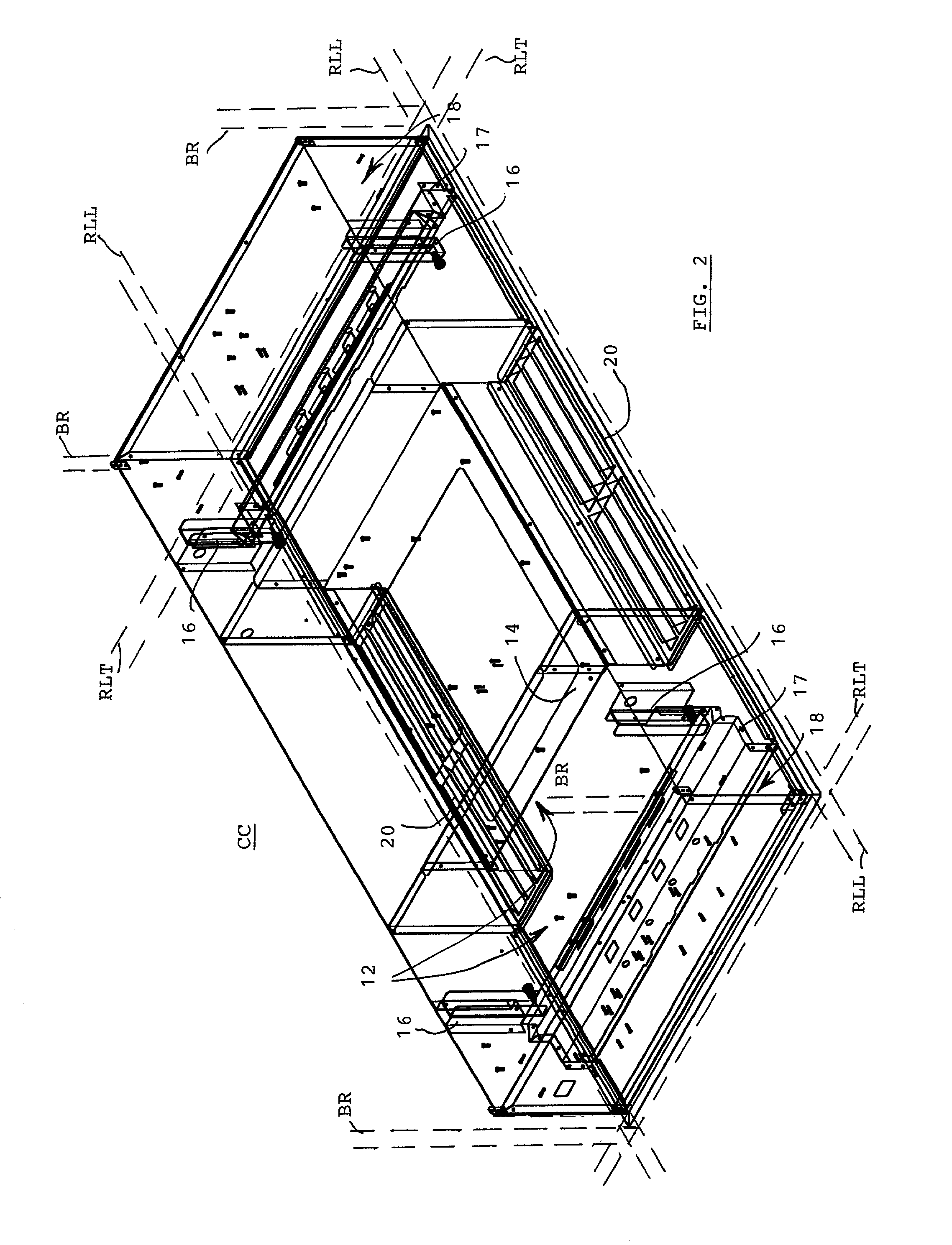
[0025] Referring to FIG. 1, a UV air cleaning and disinfecting system has an enclosed chassis CC provided with an inlet / outlet surface panel SP that faces down from a ceiling surface. The surface panel SP has a longitudinal length along axis LL and a latitudinal width along axis LT. The chassis is to be mounted in a space behind a ceiling surface of a room space with its surface panel substantially coplanar with the ceiling surface and facing into the room space. A pair of inlet vent arrays 10 formed in the inlet / outlet surface panel SP receives incoming air into the chassis. the inlet vent arrays 10 are positioned spaced apart on opposite longitudinal sides of the surface panel from each other. A pair of outlet vent arrays 20 in the surface panel delivers outgoing (cleaned and disinfected) air from the chassis. The outlet vent arrays are spaced apart on opposite latitudinal sides ofthe surface panel from each other. The four-leaf-clover pattern ofmutually circulating air streams in...


PUM

PropertyMeasurementUnit
lengthaaaaaaaaaa
lengthaaaaaaaaaa
lengthaaaaaaaaaa

Abstract

A UV air cleaning and disinfecting system has an enclosed chassis with an inlet / outlet surface panel on one planar side thereof, and the chassis is mounted in the space behind a drop ceiling with its surface panel coplanar with the ceiling surface and facing into the room space. The surface panel has a pair of inlet vent arrays on opposite longitudinal sides of the surface panel from each other, and a pair of outlet vent arrays on opposite latitudinal sides of the surface panel from each other. Arranged in the chassis are an air blower unit and an array of UV lamps. The positioning of the inlet and outlet vent arrays establish four mutually circulating air streams in a four-leaf-clover pattern in the room space, which obtains a high-efficiency throughput of air handled by the system. The UV lamp array is arranged longitudinally across the chassis between the inlet ventsat a lower elevational position ofthe chassis. A pair of air filters is arranged at intake chambers separated by UV-blocking baffles at opposite longitudinal sides of the main chamber housing the air blower in the center of the chassis at an upper elevational position from the array of UV lamps. The upward and downward movement of the air through the filters and over the UV lamps toward the center causes swirling movements which enhance the exposure of pathogens in the air to UV radiation exposure. The surface panel is formed with a series of cascading door sections to allow wide access across the center of the chassis for maintenance of the UV lamps, with a first door section connected to an interlock switch for cutting off electrical power to the UV lamps and fan when the first door section is opened. The UV-blocking baffles have an angled shape and slits at an upper flange thereof covered with fused silica shields. The system's chassis is dimensioned to fit on ceiling rails spaced at standard 4 foot length and 2 foot width intervals. The system can provide 99% or higher inactivation of pathogens in the air with 2 to 7 or more air changes per hour for standard sized rooms.

Description

SPECIFICATION[0001] This U.S. patent application claims the priority benefit of U.S. Provisional Application 60 / 219,464 filed on Jul. 17, 2000 by the same inventor, entitled Insert & Ceiling Mounted Systems for UV Air Disinfecting Unit.[0002] This invention generally relates to UV air disinfecting and cleaning units, and more particularly, to an improved system having a layout and internal configuration for high-throughput, high-volume, and highly effective air cleaning and disinfecting of pathogens in room air spaces.BACKGROUND OF INVENTION[0003] UV disinfecting units are widely used in building heating, ventilation, and air cooling (HVAC) systems to kill and remove germs, fungi, and other pathogens carried in the air in order to improved the healthiness of indoor environments. A UV disinfecting unit is typically inserted at a suitable place in the return air ducting in order to kill the pathogens before they are carried into the HVAC unit and re-delivered into the inlet ducting in...

Claims


Application Information

Patent Timeline
Patent Type & Authority Applications(United States)
IPC IPC(8): F24F1/00F24F8/22
CPCF24F3/16F24F2001/0096F24F2003/1667F24F1/0071Y02A50/20F24F8/22
Inventor KULP, JOHN C.
Owner KULP JOHN C
Why Eureka
Try Eureka