Distraction and retraction assemblies

a technology of dislocation and assembly, applied in the field of dislocation and retraction assemblies, can solve the problems of increasing the number of steps needed, reducing the likelihood of post-operative complications, and limitations inherent in the conventional self-retaining retraction used widely in surgery, so as to facilitate tissue access, minimize soft tissue injury, and minimize the effect of soft tissue injury

Inactive Publication Date: 2009-07-23
SEEX KEVIN
View PDF3 Cites 80 Cited by
  • Summary
  • Abstract
  • Description
  • Claims
  • Application Information

AI Technical Summary

Benefits of technology

[0020]The invention further relates to an assembly which performs the aforesaid retraction functions in conjunction with applied distraction of vertebrae using distraction pins and co operating sleeves so that mechanical advantage in both distraction and retraction is achieved optimising efficiency in retraction and resisting unwanted pull out of retractors.
[0022]During a surgical operation retractors are used to facilitate access to tissues. The present invention employs in one form the principle of fixation into bone (either directly or indirectly) to provide a secure anchorage and base for a retractor blade and also a stable axis for rotation of the blade within the wound without the prior art unwanted dislocations .
[0023]The invention improves tissue exposure and surgical site access and minimizes soft tissue injury, bruising etc (due to the more controlled and reduced movements against tissues) whilst allowing variable selective rotation of at least one retractor blade as required during the surgical procedure. The combined features of the ability to adjust retraction pressure and reduce tissue pressure applied by the retractors thus minimizing tissue injury while maintaining stability of the blade distinguishes the present invention from the known prior art. The direct or indirect fixation (anchorage ) to bone of a retractor prevents unwanted slippage and avoids the need for readjustment apart from the selected amount of rotation. The stable axis of rotation from within a surgical wound also imparts a mechanical advantage to retraction pressure reducing operator fatigue. Bone fixation with rotation is achieved in a number of different ways allowing application in numerous anatomical situations.

Problems solved by technology

This apparatus can reduce the number of steps needed to perform spinal surgery and can decrease the likelihood of post-operative complications.
There are limitations inherent in conventional self retaining retractors used widely in surgery and routinely in anterior spinal surgery.
This means that when retracting two sides with different resistances eg left and right sides of an anterior (front) cervical wound (trachea, larynx, ET tube, oesophagus and thyroid are on one side only) excessive forces and retraction are applied to the easy side in an effort to retract the opposite more resistant side.
This is one reason why conventional retractors slip, twist and rise up.
Placing the teeth of these retractors under the longus colli muscle (next to the spine) works to an extent and is the standard method by which retractors in the anterior (front) of the neck are secured but it is common for retractors to require repositioning several times during an operation in addition to the difficulty of securing them in the correct place initially.
The path of least resistance is up and as the retractor opens even the slight bending tends to produce a vector of force up as the blade follows the path of least resistance out of the wound leading to unwanted displacement of the retractor and therefore compromised retraction.
Repeated adjustment can and does produce unnecessary tissue injury e.g. swallowing problems or hoarseness of voice in perhaps 5-10% of anterior cervical operations.
It also wastes time and produces unnecessary bleeding.
Persons skilled in the art are aware that one of the most frustrating parts of this type of surgery is positioning and maintaining position of the retractors.
If hammered into bone via a short point fixation, then multiple rotations produces loosening and unwanted withdrawal.
Where the pins rest on their point as a simple point of leverage but without deep fixation then they are prone to slippage if knocked or an assistant surgeon is not concentrating.
Accordingly, a major disadvantage of the prior art is that there are no retraction systems in use that allow free rotation without compromising fixation.
These blades are loose and can rotate only about axis of pin, (which is not very useful) and are not adjustable.

Method used


Image

  • Distraction and retraction assemblies
  • Distraction and retraction assemblies
  • Distraction and retraction assemblies

Examples


Embodiment Construction

[0093]The present invention will now be described in more detail according to a preferred embodiment but non limiting embodiment and with reference to the accompanying illustrations.

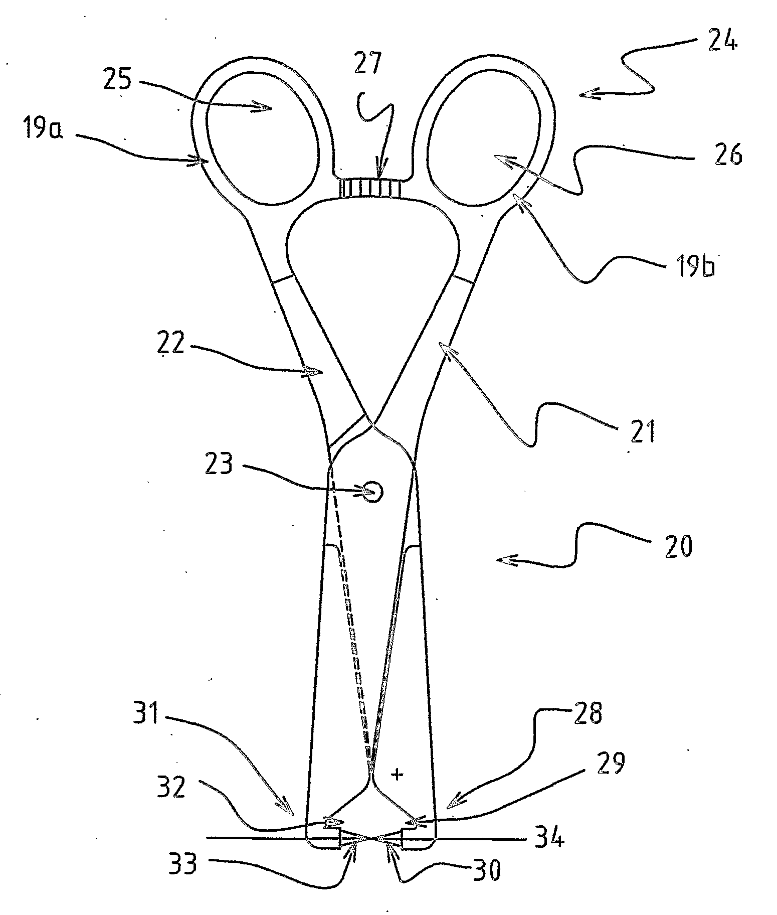
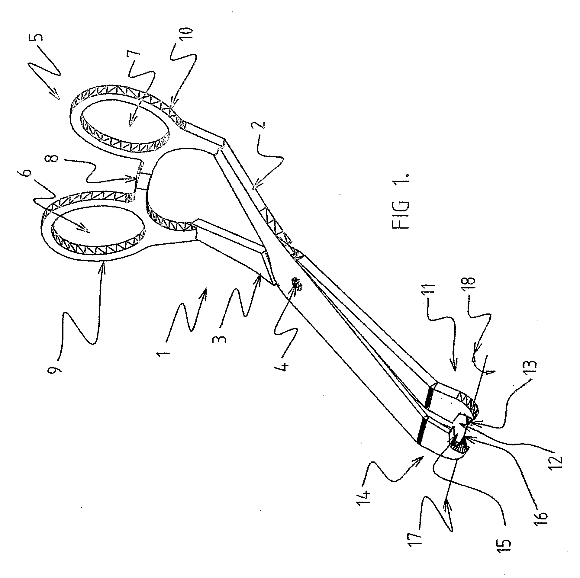
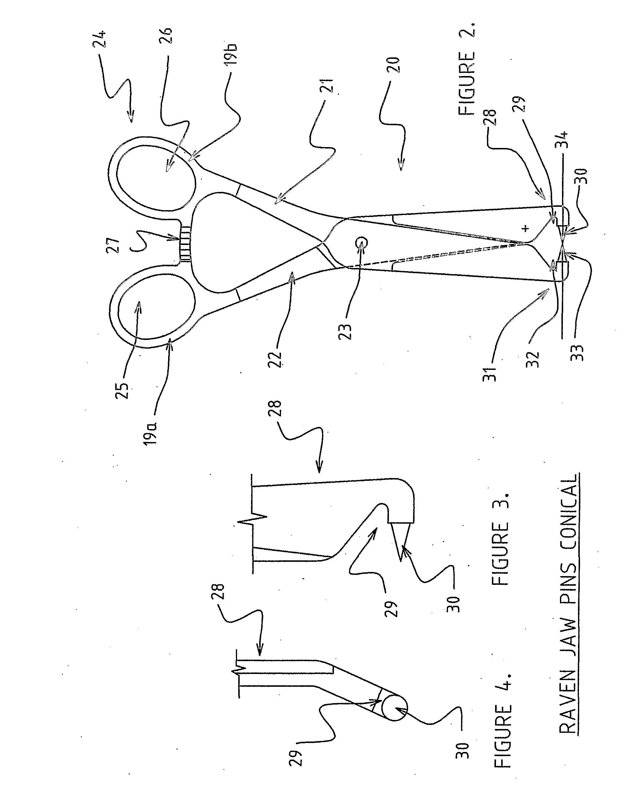
[0094]Typically according to one method, cervical distraction of vertebrae involves the use of pins temporarily fixed to the vertebrae to be distracted. Generally two pins are used one above and one below a disc or vertebral body of interest. Traditionally in a Caspar system these pins have only been used for distraction purposes via sliding tubes that fit axially over the pins and connect to an associated distraction mechanism. According to one aspect the role of the pin has been expanded to perform one or more of the following roles. The pin acts as x-ray marker to estimate a midline of a spine for cage or prosthetic disc replacement. The known and commonly used Caspar type distracter is then secured to the spine. There is however known use of distracter tubes that each slide over respective pins and w...


PUM


Abstract

An assembly (40) allowing retraction of soft tissue away from a reference plane; the assembly including at least one retracting element (51) each comprising a distal end having a formation allowing anchorage of the at least one retracting element (51). The assembly also includes a proximal end (50) of the at least one retracting element capable of movement through at least one degree of freedom relative to said anchorage.

Description

BACKGROUND[0001]The present invention relates to distraction and retraction assemblies. The invention further relates to an improved apparatus for soft tissue retraction in applications including surgery including, but not limited to spinal surgery. The invention also provides an assembly which performs the functions of distraction and retraction optimising mechanical advantage and efficiency in retraction and resisting unwanted pull out of retractors.PRIOR ART[0002]There are in existence a number of assemblies used in retraction of tissues to facilitate spinal and particularly cervical surgery.[0003]The most commonly performed anterior cervical procedure is an intervertebral fusion procedure that typically involve the steps of removing a portion or all of the affected disc material, spreading apart adjacent vertebrae with a distractor, and inserting an implant bone or cage or prosthetic disc into the space previously occupied by the removed disc material. This procedure can be done...

Claims


Application Information

Patent Timeline
Patent Type & Authority Applications(United States)
IPC IPC(8): A61B1/32
CPCA61B17/02A61B17/2812A61B2017/2808A61B2017/00261A61B2017/00473A61B17/282A61B17/0206A61B17/025
Inventor SEEX, KEVIN
Owner SEEX KEVIN
Why Eureka
Try Eureka