Repetitive progressive axial displacement pattern for phacoemulsifier needle tip

a phacoemulsifier and axial displacement technology, applied in the field of motion control of tissue emulsifier needles, can solve the problems of undesired cavitation bubbles and thermal injury of ocular tissues, and achieve the effects of reducing the undesired thermal and cavitation effects, improving the efficiency of a phacoemulsifier system, and increasing the exposure of lens fragments

Inactive Publication Date: 2005-09-06
ZACHARIAS JAIME
View PDF5 Cites 78 Cited by
  • Summary
  • Abstract
  • Description
  • Claims
  • Application Information

AI Technical Summary

Benefits of technology

[0019]An advantage of the present invention is to reduce the undesired thermal and cavitation effects when compared to currently used systems with similar degrees of lens removing capabilities. Further objects and advantages of the present invention will become apparent from consideration of the drawings and ensuing description.
[0020]A method to improve the efficiency of a phacoemulsifier system based on a novel phacoemulsification needle tip axial displacement pattern designed to increase the exposure of a lens fragment to successive strokes of ultrasonic activity of the phacoemulsification needle tip. The method also considers avoiding delivery of ultrasonic power during the periods of ultrasonic activity where minimal lens removing capabilities are known to occur.
[0021]Increased exposure of lens fragments to phacoemulsification needle tip action during each ultrasonic stroke according to the present invention is achieved by using a low frequency axial displacement carrier signal and by activating the ultrasonic energy preferably in phase with the fraction of the low frequency motion component corresponding to displacement of the tip towards the distal limit with respect to the hand-piece.

Problems solved by technology

Friction between the hollow phacoemulsification needle external walls and the surrounding elements generates undesired heat that can lead to thermal injury of the ocular tissues.
Also high intensity ultrasonic activity produces undesired cavitation bubbles.
This occurs because the high repetition rate of each stroke does not allow a lens fragment to follow the full trajectory of the phacoemulsification needle because of fragment inertia.

Method used


Image

  • Repetitive progressive axial displacement pattern for phacoemulsifier needle tip
  • Repetitive progressive axial displacement pattern for phacoemulsifier needle tip
  • Repetitive progressive axial displacement pattern for phacoemulsifier needle tip

Examples


Embodiment Construction

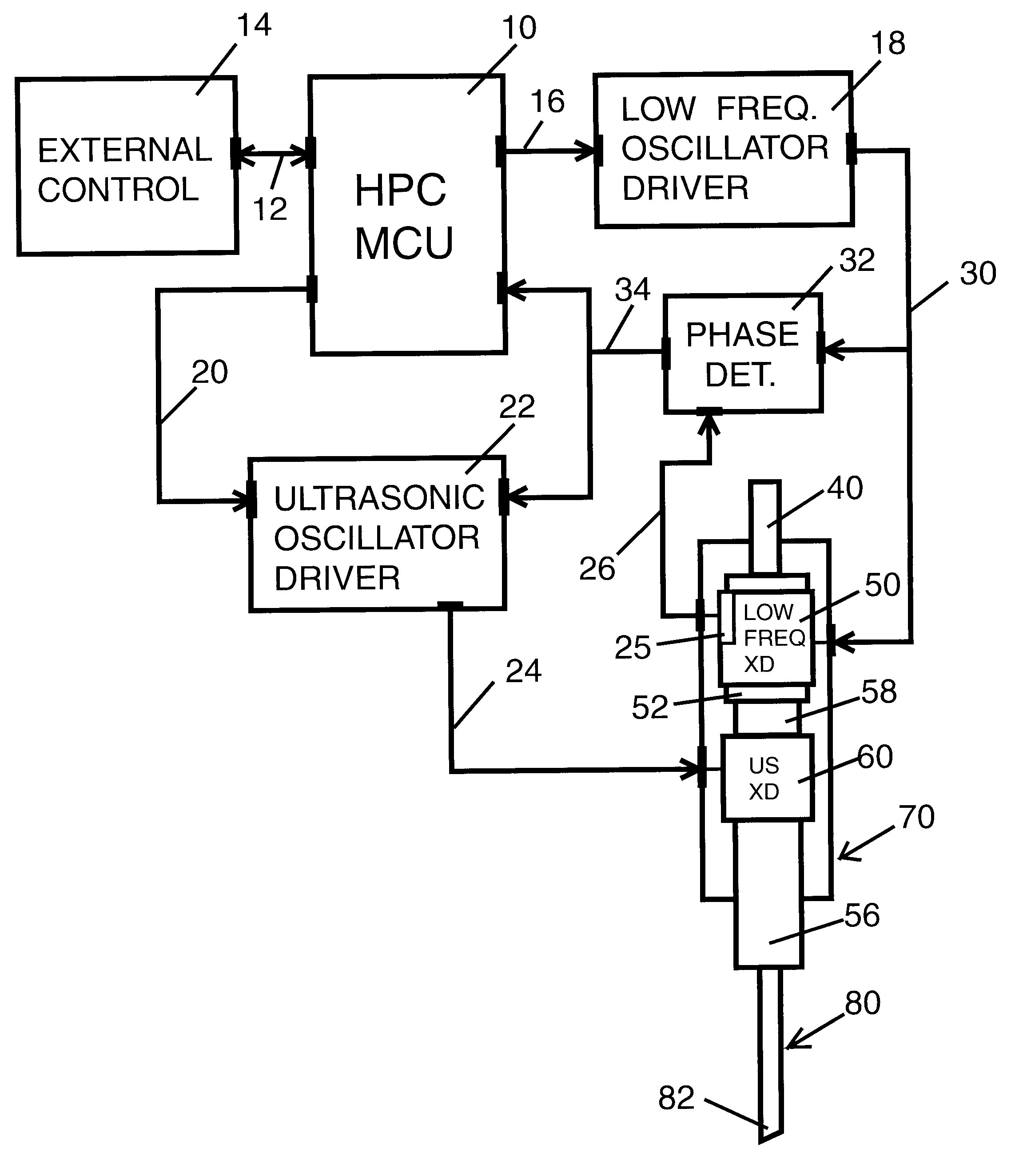
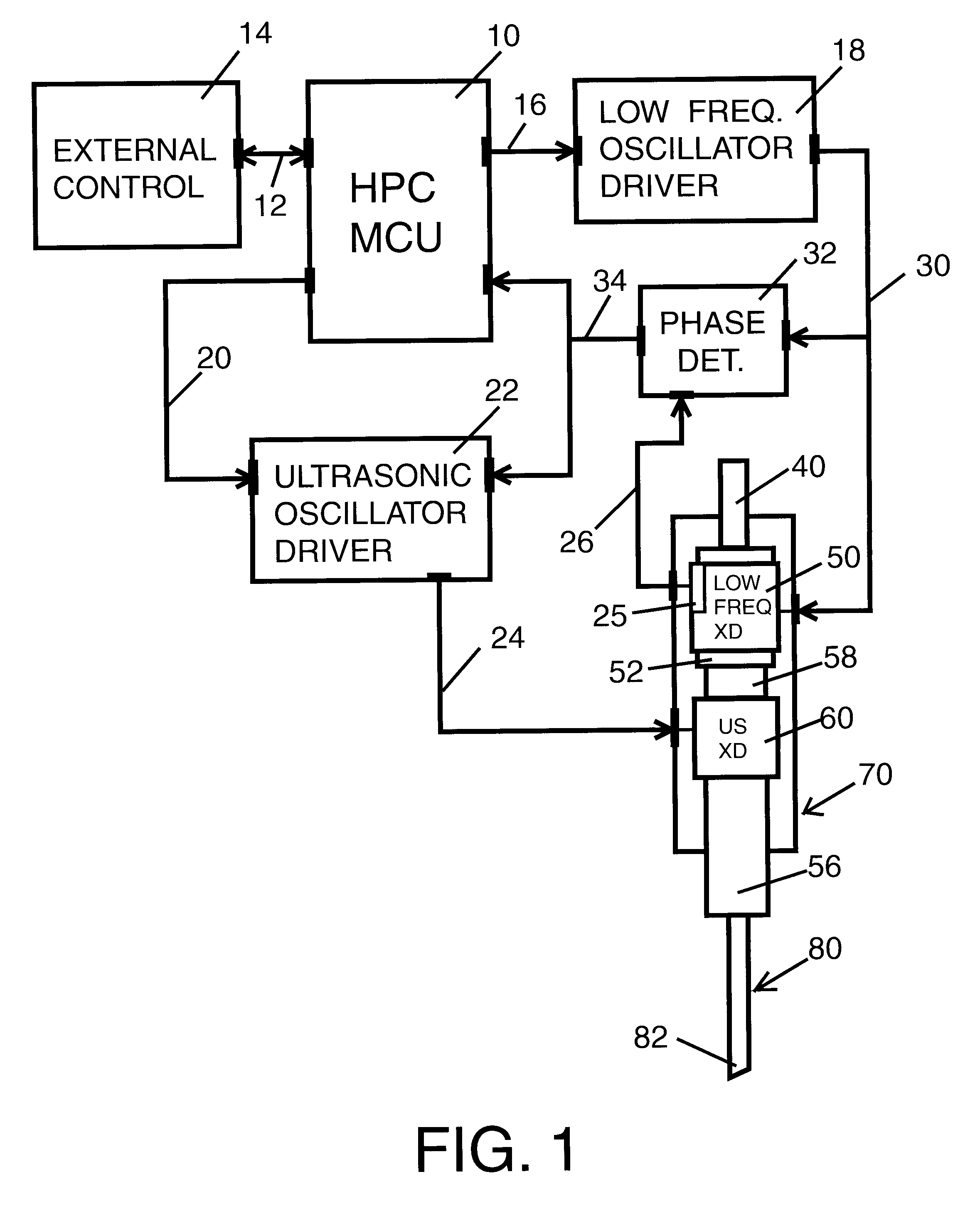
[0032]As shown in FIG. 1 a hand-piece controller unit 10 interconnects through a connector 12 to a host external controller 14. Hand-piece controller unit 10 interconnects through a connector 20 to an ultrasonic oscillator driver unit 22. Hand-piece controller unit 10 interconnects through a connector 16 to a low frequency oscillator driver unit 18.

[0033]Ultrasonic oscillator driver unit 22 connects through connector 24 to an ultrasonic electro-mechanic transducer 60 located inside phacoemulsification surgical hand-piece enclosure 70. Low frequency oscillator driver 18 connects through connector 30 to a low frequency electro-mechanic transducer 50 located inside phacoemulsification surgical hand-piece enclosure 70. Low frequency oscillator driver 18 also connects through connector 30 to low frequency phase—position detector circuit 32.

[0034]Low frequency electro-mechanic transducer 50 has an attached low frequency position sensor 25 that provides a low frequency motion component pha...


PUM


Abstract

A method to improve phacoemulsification efficiency by providing bursts of axial ultrasonic activity in synchronization with a fraction of a lower frequency axial oscillatory activity, the fraction corresponding to the portion of the low frequency signal that displaces toward the lens fragments and distally from the phacoemulsification hand-piece. Ultrasonic bursts synchronized with displacement of the phacoemulsification needle tip toward the lens tissue increases efficiency allowing the reduction of the required ultrasonic power minimizing heat generation and cavitation.

Description

BACKGROUND OF INVENTION[0001]1. Field of Invention[0002]This invention is related to motion control of a tissue emulsifier needle and more particularly to the axial displacement pattern followed by the tip of an emulsifier needle used to emulsify biological tissues such as the phacoemulsification of the crystalline lens during eye surgery.[0003]2. Description of Prior Art[0004]Current phacoemulsification apparatus usually use electro-mechanic actuators driven at sonic or ultrasonic frequencies to energize a hollow phacoemulsification needle. These actuators operate under piezoelectric, magnetostrictive or voice-coil principles.[0005]Axial sinusoidal oscillation of the phacoemulsification needle emulsifies the lens tissue of the eye during cataract surgery primarily by jackhammer action. Friction between the hollow phacoemulsification needle external walls and the surrounding elements generates undesired heat that can lead to thermal injury of the ocular tissues. Also high intensity ...

Claims


Application Information

Patent Timeline
Patent Type & Authority Patents(United States)
IPC IPC(8): A61F9/007
CPCA61F9/00745
Inventor ZACHARIAS, JAIME
Owner ZACHARIAS JAIME
Why Eureka
Try Eureka