Method for making electrically conductive textiles and textile sensor

Active Publication Date: 2016-06-30
FOOTFALLS & HEARTBEATS (UK) LTD
View PDF14 Cites 75 Cited by
  • Summary
  • Abstract
  • Description
  • Claims
  • Application Information

AI Technical Summary

Benefits of technology

[0015]In some embodiments of a textile sensor according to the present invention, resistance in the textile sensor can automatically calibrate to a stable baseline level after the textile sensor is applied to a body. In some embodiments, resistance in the textile sensor can automatically calibrat

Problems solved by technology

Constructing electrical circuits in textile materials presents a number of challenges.
Such efforts have disadvantages, such as conductive fabrics that cannot be worn against a wearer's skin or must be limited to a small surface area.
In garments having a sensor added to a fabric, design processes become complicated and manufacturing costs

Method used


Image

  • Method for making electrically conductive textiles and textile sensor
  • Method for making electrically conductive textiles and textile sensor
  • Method for making electrically conductive textiles and textile sensor

Examples


experiment a

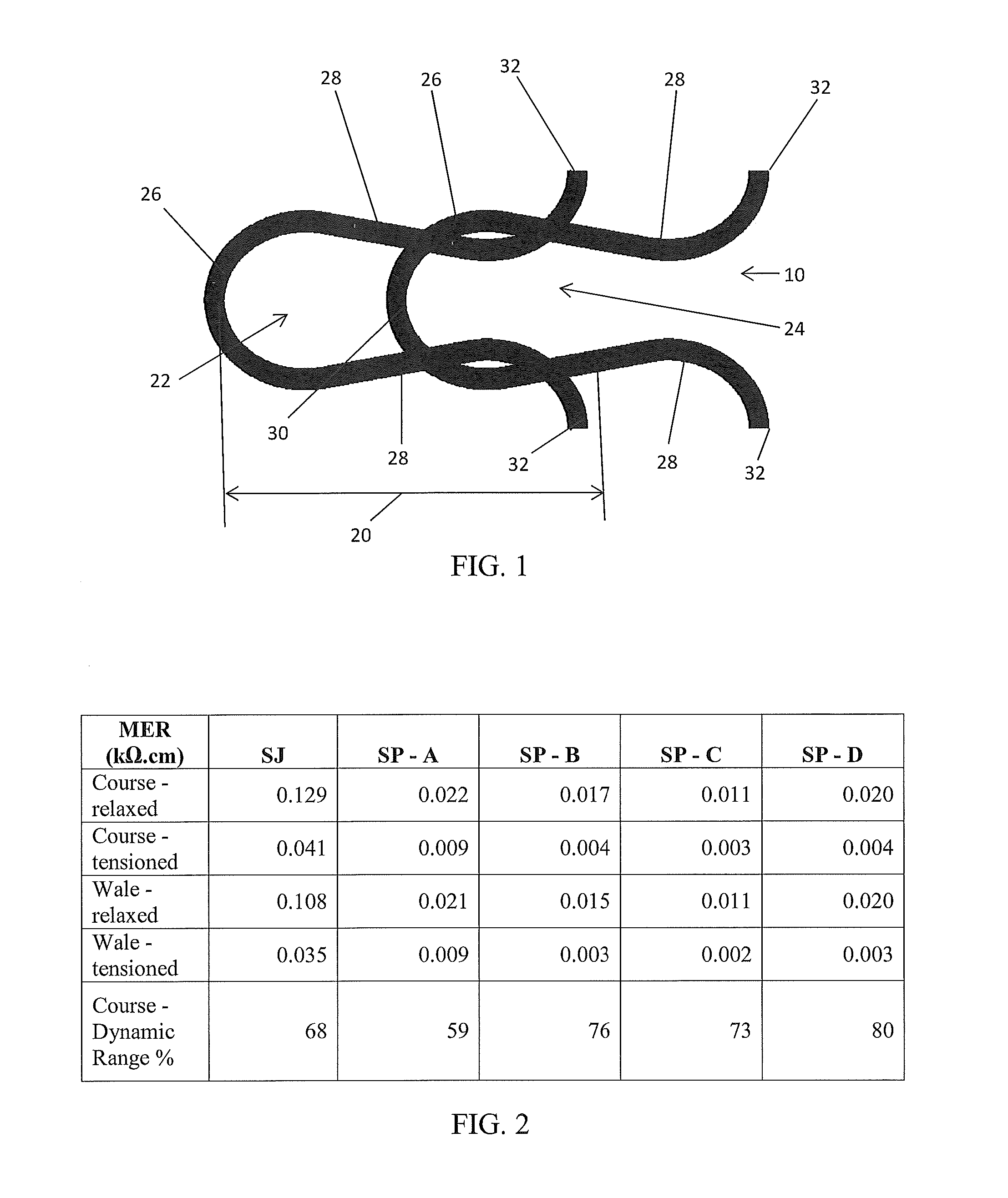
[0100]In Experiment A, mean electrical resistivity (MER), fabric thickness, and optical porosity in the four different sample stitch patterns were compared to those variables in a single jersey 10 fabric. The results of Experiment A, discussed with reference to FIGS. 2, 5A, 5B, 5C, and 6, demonstrate how stitch patterns can be selected to affect these variables so as to optimize contact resistance in a textile.

[0101]The table in FIG. 2 shows mean electrical resistivity (MER) values in a single jersey (SJ) stitch pattern 10 control and in the four different sample stitch patterns. MER is shown for each stitch pattern having either relaxed or tensioned courses or relaxed or tensioned wales. Each of the four sample stitch patterns had significantly decreased MER in both the course (horizontal) direction 80 and wale (vertical) direction 74 in comparison to single jersey 10, both in relaxed states and in tensioned states. The discovery that each of the four sample stitch patterns had a s...

experiment b

[0110]In Experiment B, four fabric swatches, approximately 100 mm×100 mm in size, were knitted on a Shima Seiki WHOLEGARMENT™ 14gg knitting machine. “GG” represents “gauge” of a knitting machine, and corresponds to the number of needles / inch. The yarn in each sample swatch was a spun staple fiber yarn (80% PES / 20% INOX®), commercially available as “S-Shield” from Schoeller. Each swatch was knitted using a different percentage combination of plain jersey stitches 10, tuck stitches 36, and miss stitches 34 (stitch patterns SP-A, SP-B, SP-C, and SP-D).

[0111]Individual sample swatches were then placed under weights in a test-rig 60, as shown in FIG. 7. The test rig 60 was constructed using 3 mm thick polymethyl methacrylate. Two stainless steel weights 62 were used, one weighing 150 gm, the other weighing 250 gm. The weights 62 were separated from the sample swatches by a non-conducting cardboard layer. One weight 62 remained in placed on the sample being tested as a base weight to keep...

experiment c

[0115]In Experiment C, two fabric swatches, approximately 300 mm×100 mm in size, were knitted on a Shima Seiki WHOLEGARMENT™ 14gg knitting machine. The yarn in each sample swatch was a spun staple fiber yarn (80% PES / 20% INOX®), commercially available as “S-Shield” from Schoeller. Each swatch was knitted using a different percentage combination of plain jersey stitches 10, tuck stitches 36, and miss stitches 34 (stitch patterns SP-A and SP-B).

[0116]This experiment involved two human subjects. Subject 1 was female weighing 61 kg and subject 2 was male weighing 79 kg. Each subject stood, balanced only on her / his right foot, on the fabric swatches comprising the sample stitch patterns. Each subject wore a sock made from a non-conducting fiber. Each fabric swatch was tested for electrical resistance at two locations—at a line directly below the ankle and at a point approximating the ball of the foot). Resistance was measured on a Q-1559 multimeter (available from Dick Smith Electronics)...


PUM


Abstract

A method for making a textile sensor and a textile sensor can include selecting a combination of variables from the group consisting of yarn variables, stitch variables, and textile variables; and knitting an electrically conductive yarn in the textile sensor in accordance with the selected combination of variables, wherein the combination of variables is selected so as to provide a controlled amount of contact resistance in the textile sensor. The method and textile can further include a capacitive textile-sensor having at least two integrally knit capacitor plate elements and having a configuration adapted for a sensing activity. Resistance in the textile sensor can automatically calibrate to a stable baseline level after the textile sensor is applied to a body.

Description

FIELD OF INVENTION[0001]The present invention relates to a method for optimizing contact resistance in electrically conductive yarns and textiles, and textiles having such optimized contact resistance. Contact resistance can be optimized for particular desired uses of a yarn or textile product by adjusting physical, chemical, and / or mechanical variables in accordance with parameters predictable for such uses.BACKGROUND[0002]Constructing electrical circuits in textile materials presents a number of challenges. Conventional electrical circuits in textiles include conductive fibers knit or woven into a fabric, and capacitance or bioelectric sensors, transducers, or the like inserted into a textile structure. Such efforts have disadvantages, such as conductive fabrics that cannot be worn against a wearer's skin or must be limited to a small surface area. In garments having a sensor added to a fabric, design processes become complicated and manufacturing costs are increased.[0003]An incr...

Claims


Application Information

Patent Timeline
IPC IPC(8): D04B1/14D04B1/24
CPCD04B1/24D04B1/14D10B2403/02431G01N27/223
Inventor MCMASTER, SIMON ADAIR
Owner FOOTFALLS & HEARTBEATS (UK) LTD
Why Eureka
Try Eureka