Information processing system, information processing apparatus, and information processing method

a technology of information processing and information processing methods, applied in the field of information processing systems, information processing apparatuses, information processing methods, and computer programs, can solve problems such as difficulty in correct adjustment of projectors and cameras, misalignment of image data projected by projectors and camera images, and differences in image siz

Inactive Publication Date: 2009-05-05
FUJIFILM BUSINESS INNOVATION CORP
View PDF6 Cites 7 Cited by
  • Summary
  • Abstract
  • Description
  • Claims
  • Application Information

AI Technical Summary

Benefits of technology

[0017]According to the present invention, the captured image data is transformed with the parameters used for transforming the positions of the points to be calibrated on to the positions of given reference points. It is therefore possible to automatically calibrate the misalignment of the projection area and the captured area caused resulting from the misalignment in the axes or field angles of the projection unit and the image data capturing unit, or the distortion due to simple scaling such as enlargement or reduction or the problem due to the parallel motion. This makes it possible to project the image data with the projection unit on arbitrary position expected by the user. A simple configuration of automatic calibration enables apparatus to be small-sized.

Problems solved by technology

Document 1, however, in the system that the projection image data projected by the projector is captured with the camera and sent to a remote location, in cases which the projector and camera are structurally or physically separated, there is a problem in that it is difficult to adjust the projector and camera correctly.
For example, there are problems in that the relative positions of the image data projected by the projector and the image data captured by the camera are misaligned due to the difference in the light axes of the projector and camera, the difference in the angle of field, or the problem in the mechanical arrangement, the difference in the image size, and the problem caused by the distortion due to scaling up or down or the distortion due to parallel displacement and rotation.
If the afore-mentioned problems are not corrected, there will cause another problem that the both of image data cannot be sent or received between the remote sites precisely.
Also, the misalignment of the projector and the camera relative to the image data can be adjusted manually from the remote site, yet there is still another problem that it takes time and efforts to adjust the misalignment.

Method used


Image

  • Information processing system, information processing apparatus, and information processing method
  • Information processing system, information processing apparatus, and information processing method
  • Information processing system, information processing apparatus, and information processing method

Examples


first embodiment

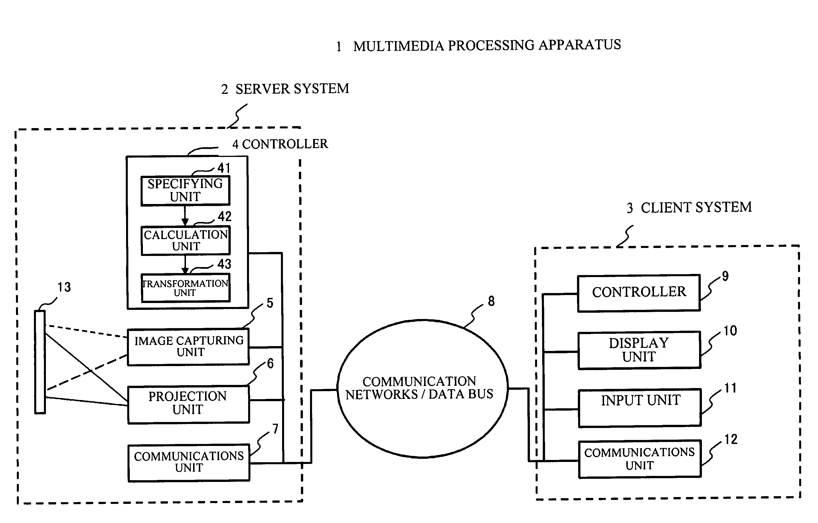
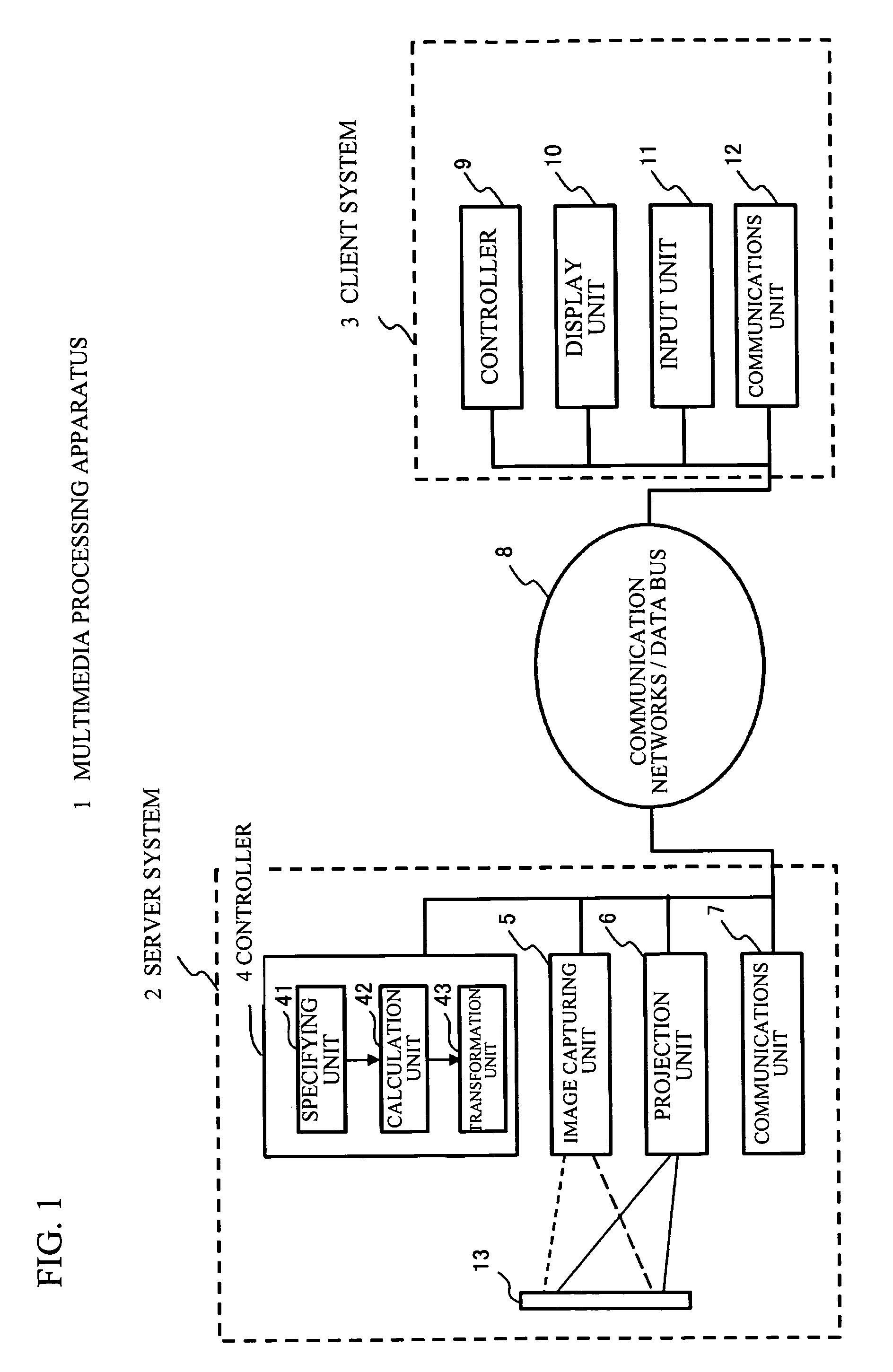
[0044]FIG. 1 schematically shows a functional configuration of a multimedia apparatus 1 in accordance with an embodiment of the present invention. Referring to FIG. 1, the multimedia apparatus (information processing system) 1 is composed a server system 2 and a client system 3. The server system 2 includes a controller (information processing device) 4, an image data capturing unit 5, a projection unit 6, and a communications unit 7; a transmitter device and a receiver device. The client system 3 includes a controller 9, a display unit 10, an input unit 11, and a communications unit 12. The server system 2 and the client system 3 are connected to each other via communication networks or a data bus 8.

[0045]The controller 4, the image data capturing unit 5, the projection unit 6, and the communications unit 7 are connected to one another via internal networks, data line, control line, or the like provided in the server system 2. In the same manner, the controller 9, the display unit ...

second embodiment

[0092]A description will now be given of a second embodiment of the present invention. In the first embodiment, the description has been given of a case where a shape of rectangle is employed for the image data for calibration. In the second embodiment, another image data for calibration will be exemplified. FIGS. 10A and 10B are views showing other examples of the image data for calibration. FIG. 10A shows image data for calibration 241 formed of four identical squares. FIG. 10B shows image data for calibration 242 formed of a hexagon having six triangles. The projection unit 6 projects the image data for calibration 241 formed of four identical squares and the image data for calibration 242 formed of a hexagon having six triangles, with the infrared lights. The image data capturing unit 5 captures the projection image data. The specifying unit 41 on the controller 4 specifies the points to be calibrated of the image data for calibration with the projection unit 6. The calculation ...

third embodiment

[0094]A description will be given of a third embodiment of the present invention. In the third embodiment, a color wheel is employed for an optical system. FIG. 12 is a view showing a projection unit 106, in which the projection unit 6 includes a color wheel. The projection unit 106 projects the image data for calibration and the projection image data in an identical optical system, whereas the image data for calibration is projected with the infrared lights and the projection image data is projected with the visible lights.

[0095]Specifically, as shown in FIG. 12, the projection unit 106 includes the visible light band data processing circuit 61, the infrared ray band data processing circuit 63, a color wheel 107, a DMD (Digital Micro mirror Device) 108, a light source 109, lenses for combination circuit 110 and 111, and a lens 112. FIG. 11 is a view showing an example of the color wheel 107. As shown in FIG. 11, the color wheel 107 is composed of a filter that corresponds to a rang...


PUM


Abstract

An information processing system includes a projection unit that projects at least image data for calibration, an image data capturing unit that captures projection image data projected by the projection unit, a specifying unit that specifies positions of points to be calibrated with the image data captured by the image data capturing unit, the positions of the points to be calibrated representing a shape of the image data for calibration, a calculation unit that calculates parameters to transform the positions of the points to be calibrated on to the positions of reference points, and a transformation unit that transforms the image data captured by the image data capturing unit with the parameters.

Description

BACKGROUND OF THE INVENTION[0001]1. Field of the Invention[0002]This invention relates to information processing systems, information processing apparatuses, information processing methods, and computer programs.[0003]2. Description of the Related Art[0004]With the progress of today's communication technology, device technology such as cameras or projectors, and computing technology, computers, cameras, and projectors are widely spreading in working places. In combination with these technologies, communication systems and computer systems are capable of supporting various types of business activities performed at remote places. For instance, teleconferencing, videotelephony, and video chatting are frequently carried out in industrial activities and in a variety of everyday life. The network system, computer, camera, and projector installed on a meeting room can support the operation of remote teleconferencing.[0005]Videoconferencing is a representative example of remote teleconferen...

Claims


Application Information

Patent Timeline
Patent Type & Authority Patents(United States)
IPC IPC(8): G03B21/00G09G5/00H04N3/23
CPCG03B21/14H04N9/3185H04N9/3194
Inventor HIRATA, KAZUTAKAIYODA, TETSUO
Owner FUJIFILM BUSINESS INNOVATION CORP
Why Eureka
Try Eureka