Positioning calibration method for construction working machines and its positioning calibration controller

a technology for construction working machines and calibration controllers, which is applied in mechanical machines/dredgers, navigation instruments, instruments, etc., can solve the problems of large accumulated errors due to accumulation of errors, inability to accurately measure, and inability to accurately calculate, etc., to achieve high accuracy, save labor for inputting, and simple and less laborious process

Pending Publication Date: 2021-09-23
TOTALMASTERS CO LTD
View PDF5 Cites 4 Cited by
  • Summary
  • Abstract
  • Description
  • Claims
  • Application Information

AI Technical Summary

Benefits of technology

[0050]According to the present invention, as a specific effect, the prism has only to be attached to one position in a case of the backhoe, and to one or two positions in a case of the bulldozer, so that the attached position(s) is(are) reduced. And, since it is stuck to the position which is ultimately desired, such as a blade top and a blade edge, the accuracy of calibration is high. And, since the system makes calculations automatically after measuring the prism with the TS, the labor for inputting is saved. In addition, even when calibration is required at the construction site, only the above-mentioned measures may be taken, and calibration work can be performed without expertise for such as data setting based on the structure of the machine. In particular, the coordinate of the machine body of the backhoe can be automatically calibrated, for example. On top of that, daily calibration can be performed accurately at the start of working with a simple and less laborious process, such as by placing the working tool to an upper rotation limit.
[0051]Even from an accuracy aspect, there is no sticking errors or their accumulation due to attachment of multiple prisms. It is not affected by irregularities, etc. coming from the structure of the machine body of the construction machine, and the accuracy is remarkably improved, because measurement and calibration can be carried out along axes of the coordinate systems can be carried out. Calibration processing is performed by the positioning system itself, regardless of external means, so calibration results can be used as is in positioning. As a result, th

Problems solved by technology

However, there may be no such information among such existing backhoes and bulldozers, in which case it is necessary to accurately measure the dimensions of machine bodies, booms, arms, buckets, blades, links (frame, push arms, etc.) that support the blades from the vehicle bodies.
However, in the field work, there is a big problem that they can not be measured accurately.
However, in this example, large error occurs, depending on the working machines, in the measurement value due to ambiguity of the measurement position of the members or the dimension of the members, so the accumulated errors due to the accumulation of those errors becomes a large problem.

Method used


Image

  • Positioning calibration method for construction working machines and its positioning calibration controller
  • Positioning calibration method for construction working machines and its positioning calibration controller
  • Positioning calibration method for construction working machines and its positioning calibration controller

Examples


example 1

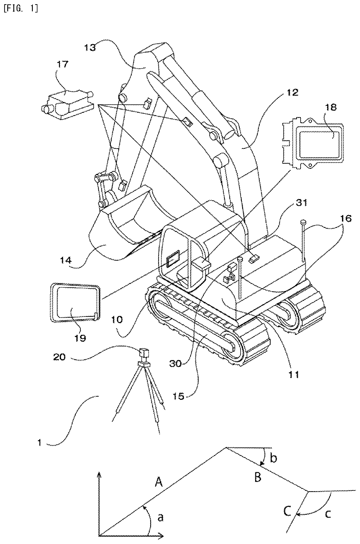
[0103]First, measurement of the drive working tool is performed under rotation. This will be performed continuously to the setting and the calibration of the machine body coordinate system. As shown in FIG. 7, for example, the prism is held on a blade tip 25 of the bucket, and the world geodesic coordinate 3 of the blade tip is measured by the total station (TS) 6. The measurements is made from a side of the backhoe. Stability of accuracy can be expected, because only the side position is measured from TS at the same depth.

[0104]As shown in FIG. 8, while the boom 12 and the arm are fixed, the bucket 14 only is rotated, and two Pi of the blade tip 25 of the bucket are measured in the global geodesic system.

[0105]Then, the arm 13 is rotated, the above is performed. The total number of measurement points is 4.

[0106]Next, the boom 12 is rotated, and the above is repeated. The total number of measurement points is 8.

[0107]O2, O3, Pi are measured and determined in advance at the upper lim...

example 2

(2) Example 2

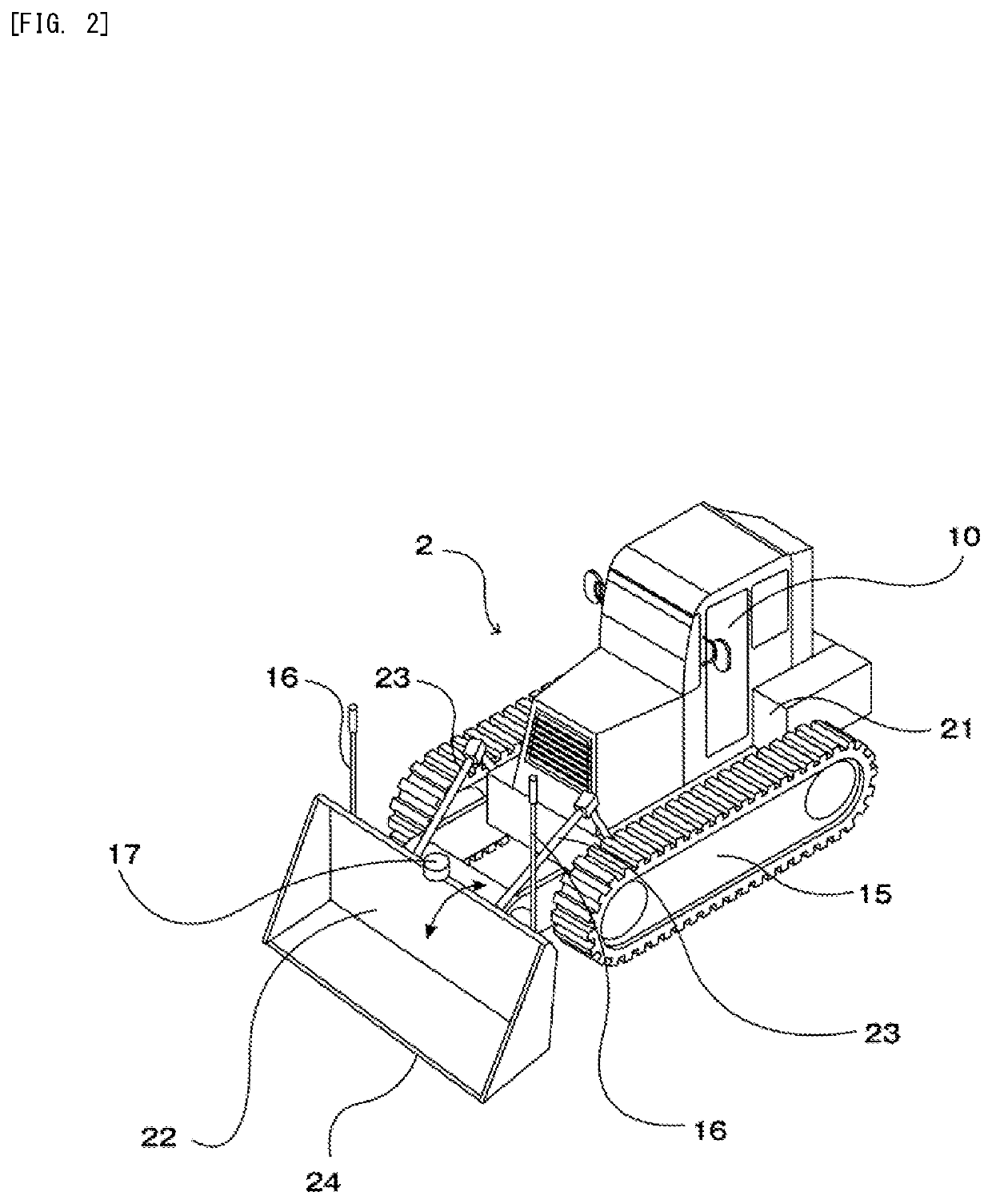
[0125]Next, an embodiment of a bulldozer will be described.

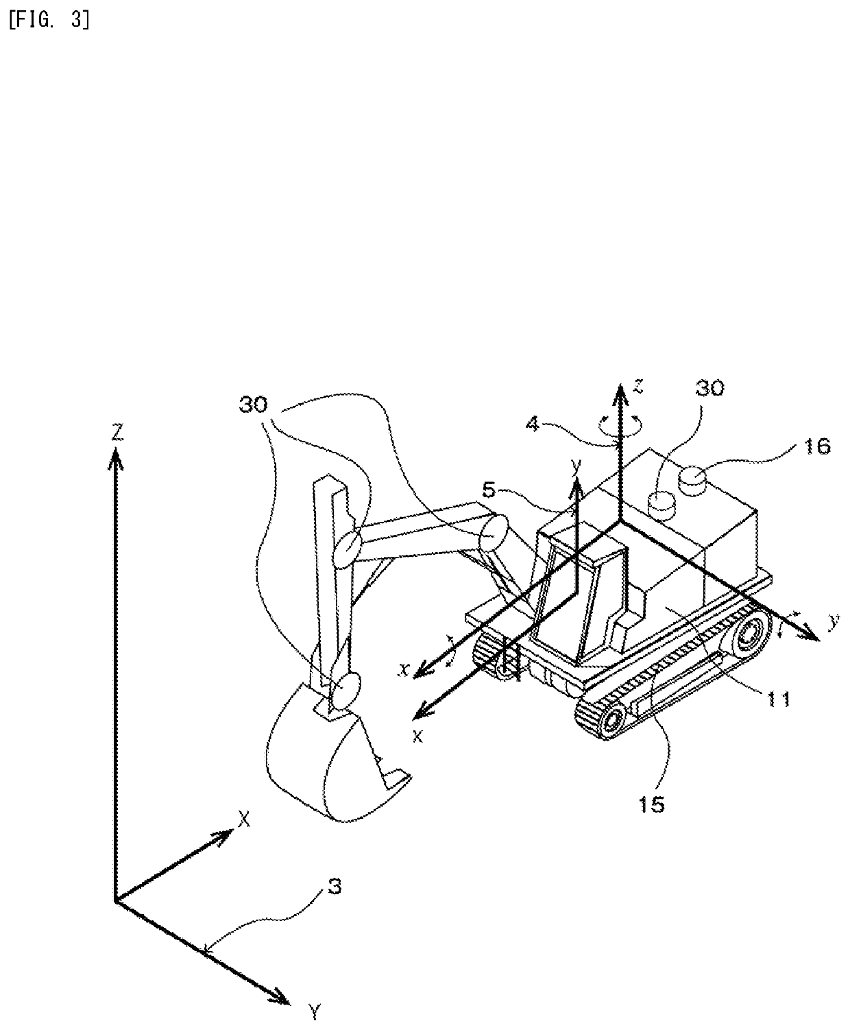
[0126]FIG. 4 is a perspective conceptual figure showing an image of the coordinate system of the entire bulldozer in the positioning calibration method and its positioning calibration controller for the construction working machine according to the embodiment of the present invention. As shown in the figure, a set of GNSS receivers 16 and antennas is installed on the machine body. (As shown in the figure, An integrated type of the GNSS receiver 16 and the antenna may be acceptable.) The IMU (Inertial Measurement Unit, inertial measuring device) 30 consisting of the 3-axis accelerometer and the 3-axis gyroscope sensor is installed on the machine body. They are mounted on the upper machine body 21 on the machine body.

[0127]As shown in FIG. 4, the similar IMU is set on top of the blade (soil removal plate) 22. According to the operating structure of the blade, the frames (push arms) 23 are rotated in reference to a...


PUM


Abstract

A positioning calibration controller for measuring and calibrating the configuration dimensions of a construction working machine having an machine body including a first surveying device for surveying the position coordinates and a movable working tool including one or more angle detecting devices, wherein the positioning calibration method and the positioning calibration controller of the construction working machine having the feature of specifying the configuration dimensions and the configuration positions of the movable business tool by the position measurement data and the angle data detected by the angle detecting device by measuring the position coordinates of the plurality of posture positions of the movable business tool by a second surveying device.

Description

TECHNICAL FIELD[0001]The present invention relates to a positioning and calibration method for construction working machines, and more particularly to simplification and accurate calibration of the positional detection of the movable working portion with GNSS.BACKGROUND[0002]Generally, in the civil engineering and the construction fields, backhoes are conventionally used as construction working machines in leveling ground, paving, etc. Backhoes are also called hydraulic excavators. Recently, in the operation of the backhoe, movement of a machine body or driving or rotation of a boom, an arm, a bucket, etc. as an upper drive body (movable working portion or movable working member, also referred to as a drive working tool) is specified, and automatically controlled in accordance with the shape of the field leveling, or machine guidance control is performed to assist an operator in the operation. To perform such a control, it is necessary to accurately grasp the position (coordinate) o...

Claims


Application Information

Patent Timeline
IPC IPC(8): G01S19/23G01C15/00G01C25/00
CPCG01S19/23G01C25/00G01C15/00E02F3/32E02F3/36E02F3/435E02F3/76E02F3/84G01S19/42G01C21/165E02F9/264G01S19/235
Inventor TAMAZATO, YOSHINAO
Owner TOTALMASTERS CO LTD
Why Eureka
Try Eureka