Sheet conveying apparatus and image forming apparatus

Inactive Publication Date: 2005-02-17
CANON KK
View PDF34 Cites 41 Cited by
  • Summary
  • Abstract
  • Description
  • Claims
  • Application Information

AI Technical Summary

Benefits of technology

[0019] Therefore, the present invention has been made in view of the aforementioned circumstances, and it is an object of the present invention

Problems solved by technology

However, in such a loop registration process, a loop space for forming a loop is always required, which results in an increase in a size of the apparatus.
In addition, when a sufficient loop space cannot be secured, there are problems in that jam (paper jam) due to buckling occurs, in particular, in a sheet such as thin paper with low rigidity and sound (so-called loop sound) is generated when the sheet is brought into abutment against the registration roller pair.
Moreover, there is another problem in that skew conveying correction ability changes depending upon rigidity of a sheet.
More specifically, in the case of the sheet such as thin paper with low rigidity, an abutting pressure at the time when the leading edge of the sheet is brought into abutment against the registration roller nip may be insufficient, which results in insufficient abutment of the leading edge of the sheet against the registration roller pair.
In such a case, skew conveying correction cannot be performed completely.
In addition, in the case of a sheet such as thick paper with high rigidity, there is a deficiency in that the sheet thrusts through the nip of the registration roller pair due to an impact of abutment of the sheet against the nip of the registration roller pair.
If a load or the like is applied to the registration roller pair by, for example, a brake member in order to overcome this deficiency, which results in an increase in product cost.
Further, for examp

Method used


Image

  • Sheet conveying apparatus and image forming apparatus
  • Sheet conveying apparatus and image forming apparatus
  • Sheet conveying apparatus and image forming apparatus

Examples


first embodiment

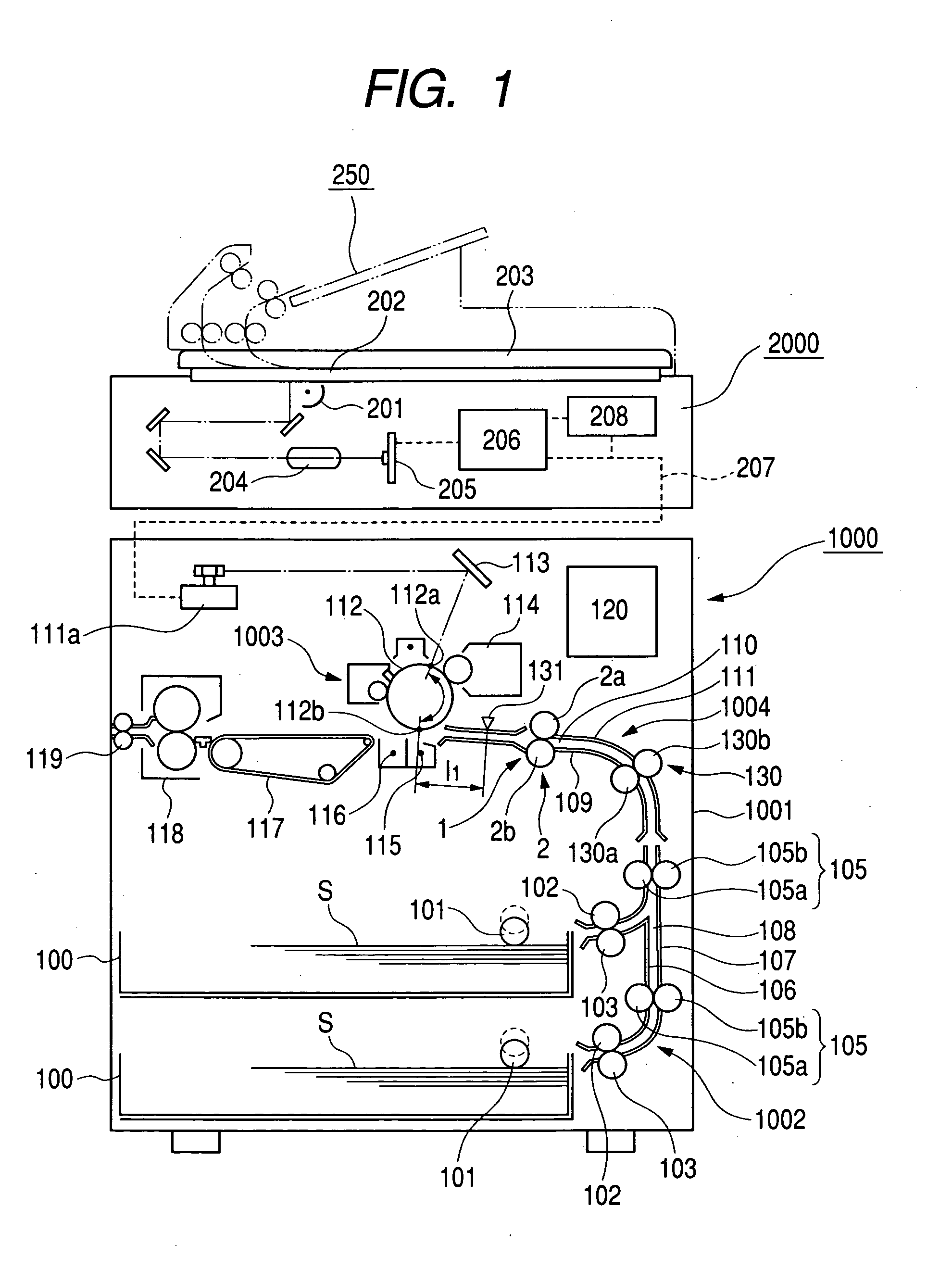
[0047]FIG. 1 is a sectional view of a printer that is an example of an image forming apparatus including a sheet conveying apparatus in accordance with the present invention.

[0048] In the figure, reference numeral 1000 denotes a printer. The printer 1000 includes a printer main body 1001 and a scanner 2000 that is arranged on an upper surface of the printer main body 1001.

[0049] Here, the scanner 2000 for reading an original includes a scanning optical system light source 201, a platen glass 202, an original pressing plate 203 that opens and closes, a lens 204, a light-receiving element (photoelectrical conversion element) 205, an image processing portion 206, a memory portion 208 for storing an image processing signal of an image processed in the image processing portion 206, and the like.

[0050] In reading an original, the scanner 2000 reads the original such that an original (not shown) placed on the platen glass 202 is irradiated with light from the scanning optical system ligh...

second embodiment

[0093] Next, the present invention will be explained.

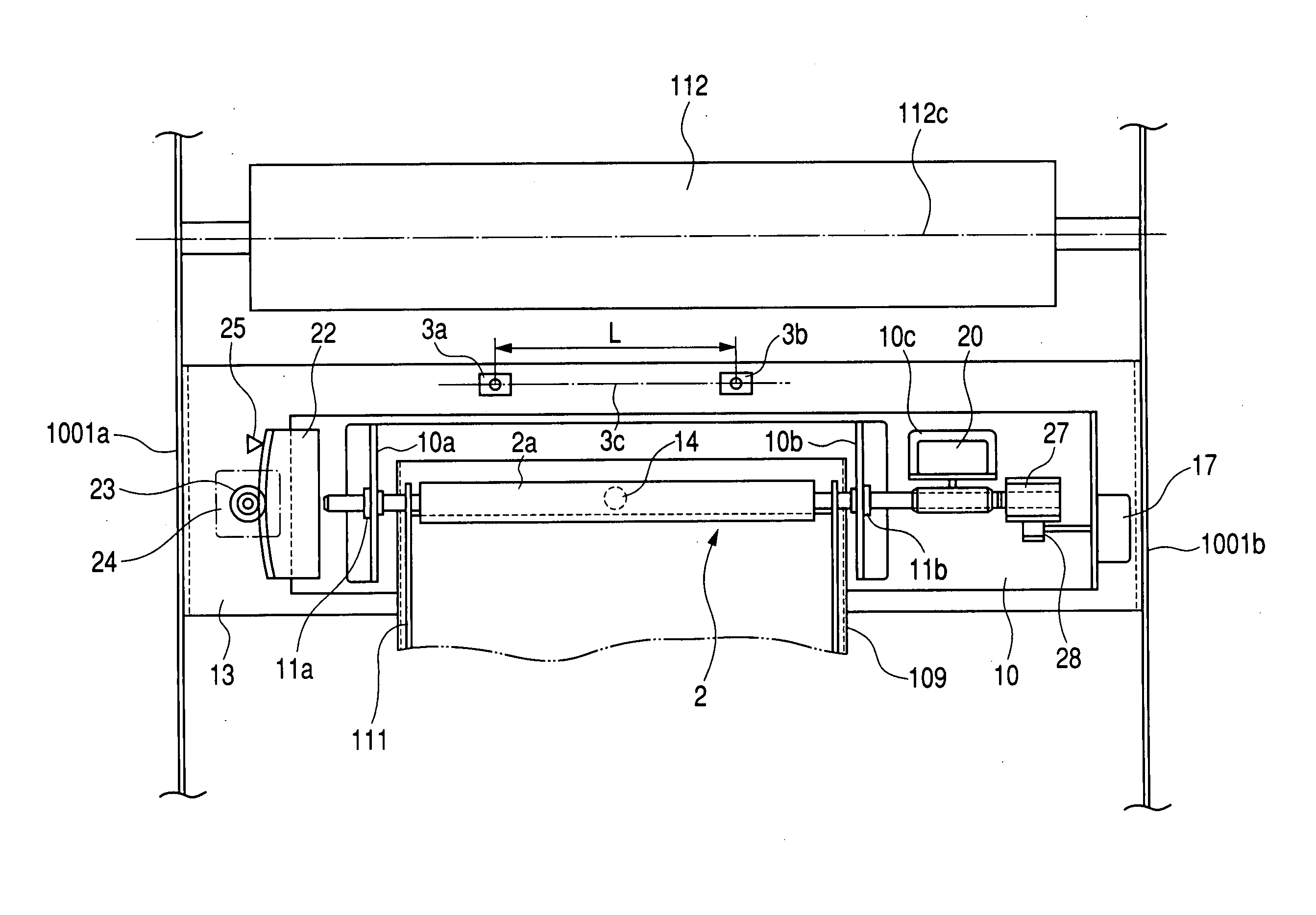
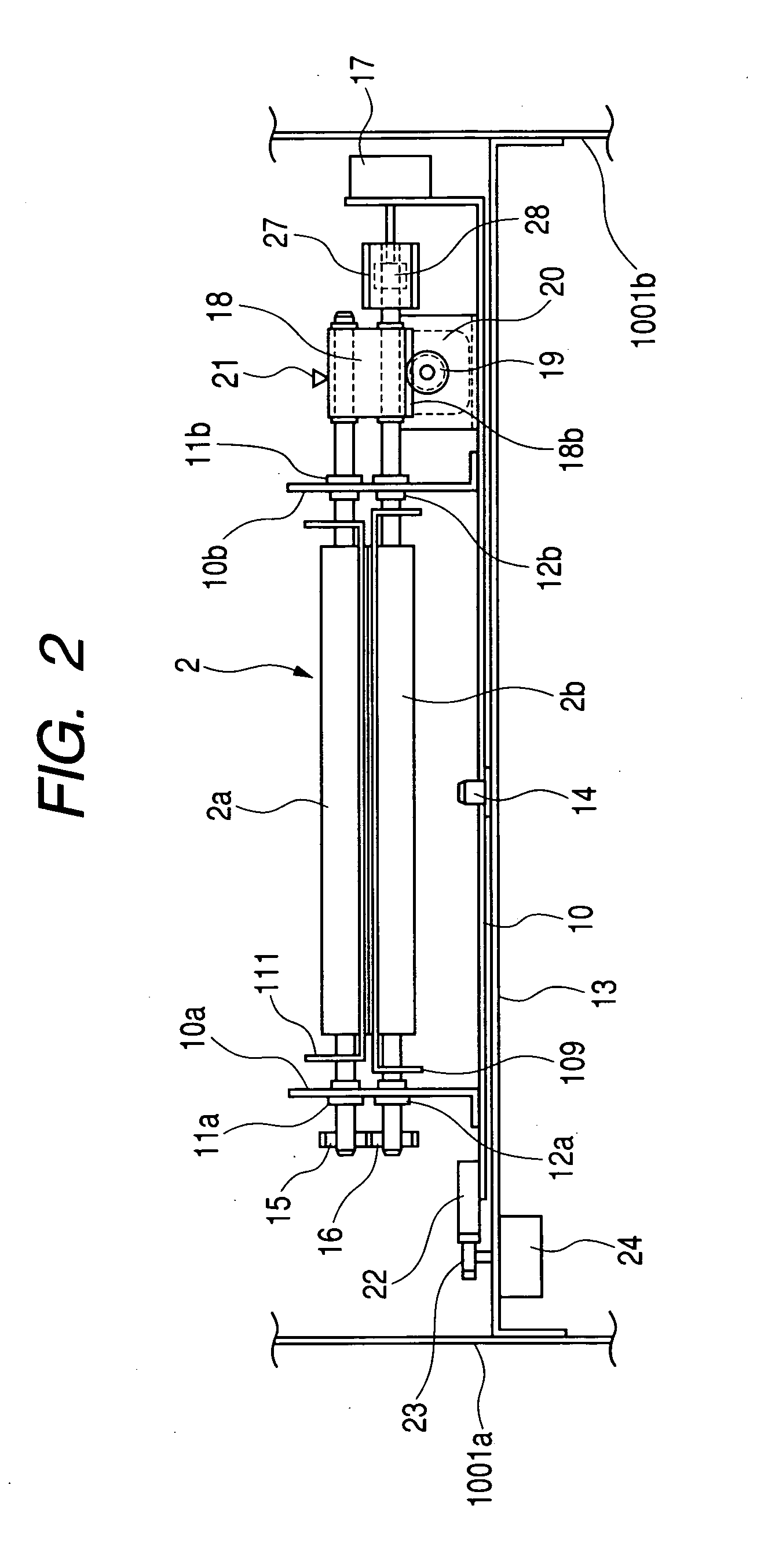
[0094]FIG. 9 is a side view of a skew correction roller portion of a sheet conveying apparatus in accordance with this embodiment, and FIG. 10 is a plan view of the same. Note that, in FIGS. 9 and 10, reference numerals and symbols identical with those in FIGS. 2 and 3 denote identical or equivalent portions.

[0095] In FIGS. 9 and 10, reference numeral 150 denotes an upper guide serving as guide means, which forms an upper surface of the sheet conveying path 110 that curves along the lower guide 109. The upper guide 150 is provided pivotally in the vertical direction with a stay shaft 1001c fixed to a front side plate 1001a and a rear side plate 1001b as a fulcrum. The upper upstream roller 130b of the two upstream rollers 130a and 130b constituting the upstream roller pair 130 is rotatably held in the upper guide 150.

[0096] Note that the upper guide 150 is biased in a direction of the lower guide 109 by biasing means (not shown)...

third embodiment

[0119] Next, the present invention will be explained.

[0120]FIG. 16 is a plan view of a skew correction roller portion of a sheet conveying apparatus in accordance with this embodiment. Note that, in FIG. 16, reference numerals and symbols identical with those in FIG. 8 denote identical or equivalent portions.

[0121] In the figure, reference symbol 130c denotes an upper upstream roller constituting the upstream roller pair 130. At least the upper upstream roller 130c is supported rotatably and movably in a thrust direction to the upper guide 111. Note that the upper upstream roller 130c is usually held in a predetermined position shown in the figure by the action of biasing springs 31a and 31b that bias the upper upstream roller 30c inwardly, respectively.

[0122] In this way, at least the upper upstream roller 130c constituting the upstream roller pair 130 is constituted movably in the thrust direction. Therefore, when the sheet S rotates as described above at the time of skew convey...


PUM


Abstract

To provide a sheet conveying apparatus capable of improving a correction accuracy for conveying a sheet. Accordingly, a “sheet conveying apparatus for conveying a sheet using a sheet conveying unit arranged along a sheet conveying path” according to the present invention includes a skew detecting unit for detecting skew of the sheet conveyed along the sheet conveying path with respect to a sheet conveying direction, a skew correcting unit that moves in a direction for correcting the skew of the skewed sheet with the sheet nipped therein on the basis of a detection signal from the skew detecting unit, and a guide unit for regulating side edges of the sheet and guiding the sheet to the skew correcting unit, in which, when the skew correcting unit moves in the direction for correcting the skew of the sheet, the guide unit is moved in the direction for correcting the skew of the sheet.

Description

[0001] This application claims priority from Japanese Patent Application No. 2003-200735 filed on Jul. 23, 2003, which is hereby incorporated by reference. BACKGROUND OF THE INVENTION [0002] 1. Field of the Invention [0003] The present invention relates to a sheet conveying apparatus that has a structure for correcting skew of a sheet such as recording paper or an original to be conveyed to an image forming portion. [0004] 2. Related Background Art [0005] Conventionally, image forming apparatuses or image reading apparatuses such as a copying machine, a printer, a facsimile machine, and a scanner include a sheet conveying apparatus that conveys a sheet such as recording paper or an original to an image forming portion or an image reading portion. The sheet conveying apparatus may be provided with correcting means for performing skew conveying correction for a sheet or positional deviation correction for a sheet in order to adjust a posture and a position of the sheet before conveyin...

Claims


Application Information

Patent Timeline
IPC IPC(8): B65H5/06G03G15/00B65H5/36B65H7/08B65H9/00B65H9/16
CPCB65H9/002B65H9/16B65H2404/14212B65H2511/212B65H2511/242B65H2220/02B65H2220/11B65H2220/01B65H2511/24
Inventor SUGA, TAKESHIINOUE, HIROSHIGE
Owner CANON KK
Why Eureka
Try Eureka