
On-track correcting device of space-borne phased array transmitting antenna

A technology of transmitting antenna and correction device, which is applied to antennas, antennas suitable for movable objects, electrical components, etc., can solve the problems of unsuitability for aerospace engineering transplantation, long interruption time of satellite communication, and high error calculation complexity. Guaranteed beamforming effect, less computation, and faster convergence

Inactive Publication Date: 2011-02-02
SHANGHAI INST OF MICROSYSTEM & INFORMATION TECH CHINESE ACAD OF SCI
View PDF3 Cites 43 Cited by
  • Summary
  • Abstract
  • Description
  • Claims
  • Application Information

AI Technical Summary

Problems solved by technology

[0004] At present, when the phased array antenna is calibrated on the ground, the maximum mean square criterion (LMS) adaptive correction method is often used to calculate the amplitude and phase errors. However, the error calculation complexity of this method is high, which is not suitable for aerospace engineering transplantation, and the convergence time Long, the interruption time of satellite communication due to correction is relatively long

Method used


Image

  • On-track correcting device of space-borne phased array transmitting antenna
  • On-track correcting device of space-borne phased array transmitting antenna
  • On-track correcting device of space-borne phased array transmitting antenna

Examples


Embodiment Construction

[0015] In order to make the purpose and features of the present invention more comprehensible, the specific implementation manners of the present invention will be further described below in conjunction with the accompanying drawings.

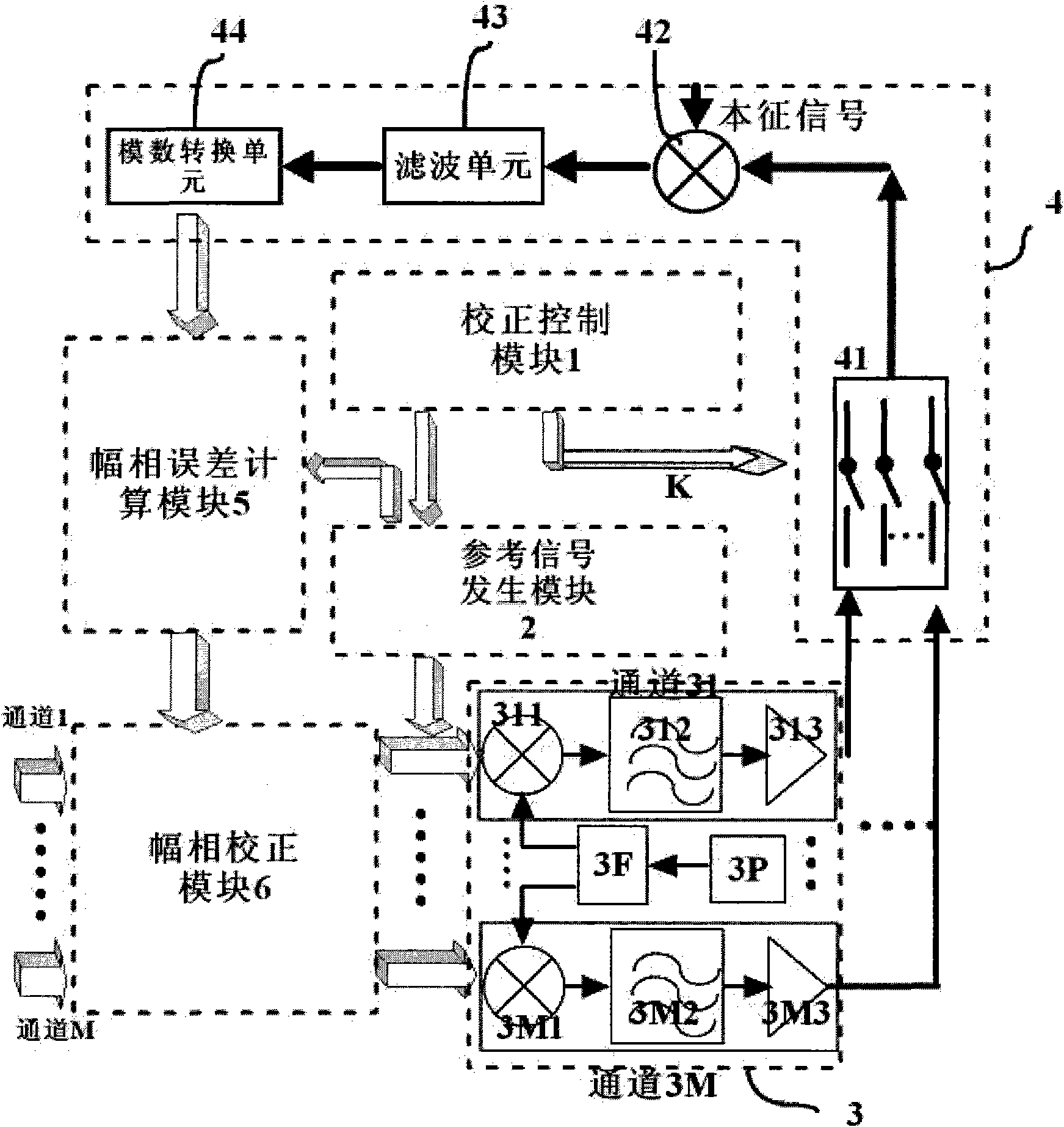
[0016] see figure 1 , figure 1 A schematic structural diagram of an on-orbit correction device for a spaceborne phased array transmitting antenna of the present invention is shown. figure 1 Among them, the on-orbit correction device includes a correction control module 1, a reference signal generation module 2, a multi-channel radio frequency transmission front-end module 3, a radio frequency feedback module 4, an amplitude and phase error calculation module 5, and an amplitude and phase correction module 6. Combine below figure 1 Describe the function and structure of each module.

[0017] The entire on-orbit correction function is started by the correction control module 1 . In this embodiment, the correction control module 1 can start th...


PUM


Abstract

The invention discloses an on-track correcting device of a space-borne phased array transmitting antenna, which is characterized in that on-track correcting is started by a correcting control module to trigger a reference signal generation module to generate correcting reference signals; radio frequency transmitting signals are output after the correcting reference signals are processed by the radio frequency transmitting front terminals of each channel of a multi-channel radio frequency transmitting front terminal module; the radio frequency transmitting signals of some channel are fed back by a radio frequency feedback module; the digitized feedback signals of the channel are output after being processed; an amplitude-phase error calculation module calculates the amplitude and the phase error between the feedback signals and the correcting reference signals of the channel according the maximum likelihood estimation rule; an amplitude-phase correcting module compensates the amplitude and the phase error of the channel according to the amplitude and the phase error obtained by calculation; and the channels are successively compensated in this way, and the amplitudes and the phases of the channels approach to be consistent.

Description

technical field [0001] The invention relates to the technical field of electronic communication, in particular to an on-orbit calibration device for a spaceborne phased array transmitting antenna. Background technique [0002] The spaceborne antenna is an important part of the satellite payload and has an extremely important impact on the performance of the entire satellite communication system. In the 1990s, phased array technology began to be used in communication satellites, which has the advantages of low loss and large-angle dynamic scanning. Moreover, it is easy to realize multi-beam coverage on the surface of the earth by using the space diversity effect of the array antenna, thereby improving the gain of the antenna. In addition, through frequency reuse between beams, the user capacity of the satellite communication system can be greatly improved. Therefore, many satellite constellation systems have adopted phased array antenna technology, such as Global Star and I...

Claims


Application Information

Patent Timeline
Patent Type & Authority Applications(China)
IPC IPC(8): H01Q3/26H01Q1/28
Inventor 梁广龚文斌余金培刘会杰覃维引
Owner SHANGHAI INST OF MICROSYSTEM & INFORMATION TECH CHINESE ACAD OF SCI
Learn More