
A soft material cutting machine

A soft material, cutting machine technology, applied in metal processing and other directions, can solve problems such as high cost, unfavorable practical use, complex structure, etc., and achieve the effects of low work efficiency, improved work efficiency, and savings in transmission mechanisms

Active Publication Date: 2018-09-14
HANGZHOU ECHO SCI TECH
View PDF3 Cites 0 Cited by
  • Summary
  • Abstract
  • Description
  • Claims
  • Application Information

AI Technical Summary

Problems solved by technology

The structure is complicated and the cost is high, which is not conducive to practical use

Method used


Image

  • A soft material cutting machine
  • A soft material cutting machine
  • A soft material cutting machine

Examples


Embodiment Construction

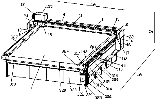
[0047] The present invention will be further described in detail below in conjunction with the accompanying drawings and examples. The following examples are explanations of the present invention and the present invention is not limited to the following examples. In this embodiment, the installation direction along the beam is the Y direction, the horizontal direction perpendicular to the Y direction is the X direction, and the vertical direction is the Z direction. All orientation descriptions in this manual use figure 1 The middle Y beam 1 is used as the reference system.

[0048] Example.

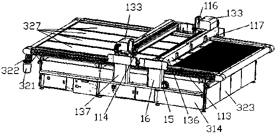
[0049] In this embodiment, the beam is a Y-direction beam 1 , and the multi-beam mechanism includes a main beam 113 and a slave beam 114 , both of which are Y-direction beams 1 . The multi-beam mechanism is a double-beam mechanism. In order to clearly illustrate the double beam mechanism, figure 1 A single beam mechanism is used for illustration, figure 2 A double beam mechanism is...


PUM


Abstract

The invention relates to a flexible material cutting machine. The flexible material cutting machine comprises a multi-cross-beam mechanism, an intelligent collision avoidance mechanism and a platform cell mechanism, wherein the multi-cross-beam mechanism comprises a plurality of cross beams, guide rails and racks, the cross beams are parallel with each other, each cross beam comprises a cross beam upper part and a cross beam lower part which are vertically mounted, each cross beam lower part comprises a left end plate and a right end plate, and the left end plate and the right end plate are mounted at the two sides of each cross beam upper part; the intelligent collision avoidance mechanism comprises intelligent collision avoidance groups, each intelligent collision avoidance group comprises a magnet collision avoidance device and a magnetic probe collision avoidance device, and an optical probe is mounted on each magnet collision avoidance device or magnetic probe collision avoidance device; the platform cell mechanism is spliced by a plurality of platform cells, and the platform cells are cell large platforms or cell small platforms; and the cross beams are paved on the platform cells, and the intelligent collision avoidance groups are mounted at the two ends of the cross beams.

Description

technical field [0001] The invention relates to a cutting machine, in particular to a soft material cutting machine. Suitable for cutting all flexible materials and plexiglass sheets. Background technique [0002] Our company's original cutting machine is driven by synchronous belt. When the machine is lengthened or widened, the synchronous belt will be stretched and deformed, which will affect the cutting accuracy. Debris is not easy to clean up and eventually leads to loss of precision. Originally, acrylic was used as the material to place the platform, but acrylic has a large temperature drift and is easy to deform. When the deformation is large, the tool will inevitably cut the felt pad, which is a serious waste. [0003] Chinese patent 201510179493.4 discloses a cutting machine, including: a material box, a cutting device, and a conveying device. The material box is suitable for holding the material tape to be cut. The cutting device is located outside the material bo...

Claims


Application Information

Patent Timeline
Patent Type & Authority Patents(China)
IPC IPC(8): B26D7/20B26D7/01B26D7/22B26D5/02
CPCB26D5/02B26D7/018B26D7/20B26D7/22
Inventor 方云科张广垒
Owner HANGZHOU ECHO SCI TECH
Learn More