Method to control anodic current in an x-ray source

a technology of anodic current and x-ray source, which is applied in the field of x-ray systems, can solve the problems of reducing the radiation dose to the patient, the most difficult to address, and the delay is undesirable,

Inactive Publication Date: 2008-04-29
DENTAL IMAGING TECH +1
View PDF10 Cites 9 Cited by
  • Summary
  • Abstract
  • Description
  • Claims
  • Application Information

AI Technical Summary

Benefits of technology

[0018]An advantage of the present invention is that it can automatically calibrate a control parameter for a filament.
[0019]A further advantage of the present invention is that automatic calibration can be performed for different combinations of technique factors used with the dental x-ray device.

Problems solved by technology

One of the problems—indeed probably the most challenging to address—which must be resolved in order to implement such accurate regulation, occurs at the onset of the electron emission.
Due to the thermal inertia of the filament, and the fact that its initial electrical resistance is low and so is the power it dissipates, normally it takes several hundreds of milliseconds for the x-ray tube to reach electrical equilibrium.
This delay is undesirable especially with modern digital x-ray image receptors, which may require, or take advantage of, short exposure time, and consequently reduce the radiation dose to the patient.
This individual adjustment is due to the very steep and critical dependence of the anodic current to an electrical current and temperature of the filament, as already mentioned, whereas minor physical and material differences between actual filaments and x-ray tubes (well within the constructive tolerances practically achievable) may lead to a significant difference among such onset anodic current.
Typically, such transitory fluctuations may last for several hundredths or even tenths of a second, which is a time frame incompatible with the short exposure time required with digital electronic image sensors, or even with “fast films”.
In the extreme case, such transitory fluctuations may bring anodic current out of scale, that is, beyond the range permitted by electrical safety controls, and cause the system to abort emission.
Such calibration is critical and easily subject to operator errors.
Consequently, even if a correction is applied to the preheating power to account for different technique factors, such correction may not operate exactly in the same manner, and equally well, in each individual unit.
In addition, such adjustment may not be stable as a result of changing environmental conditions, and may likely drift over the life span of the x-ray tube as a consequence of the filament aging.
This problem has no known solution with the usual design in the current art, except performing regular calibration re-adjustments.

Method used


Image

  • Method to control anodic current in an x-ray source
  • Method to control anodic current in an x-ray source
  • Method to control anodic current in an x-ray source

Examples


Embodiment Construction

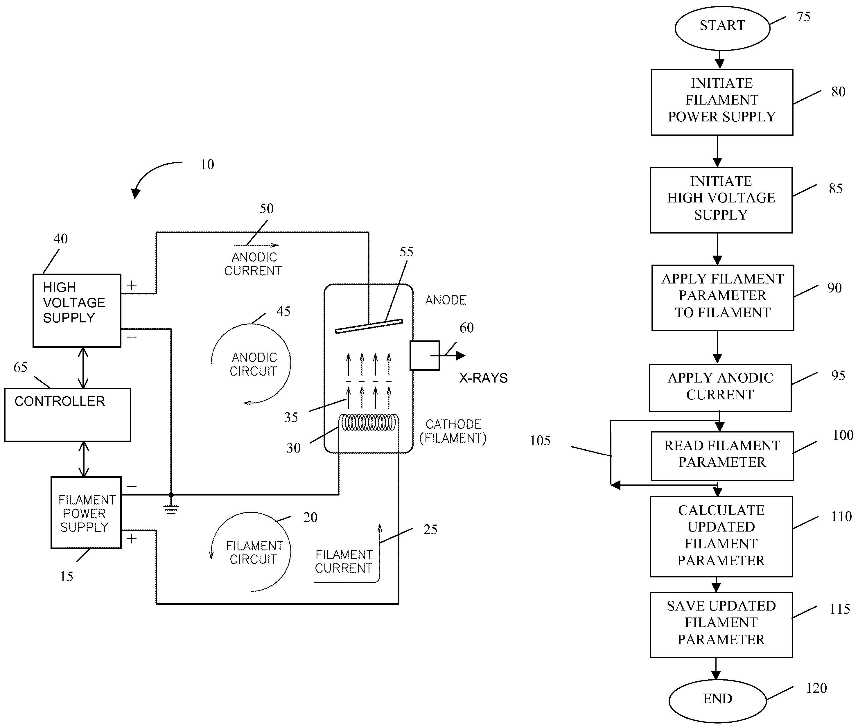
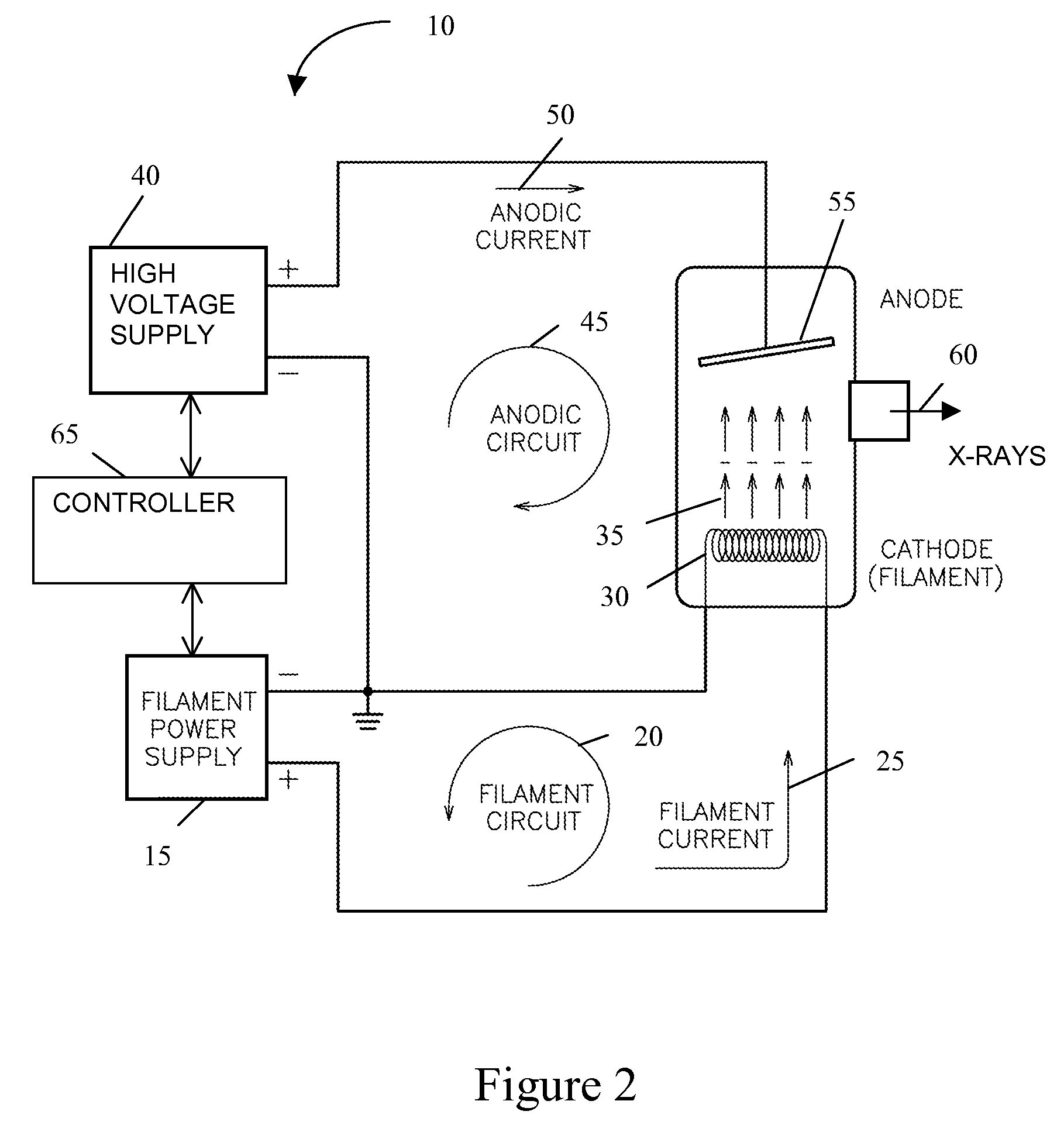
[0025]One embodiment of a dental apparatus 10 of the present invention is depicted in FIG. 2. Preferably, the dental apparatus 10 includes a filament power supply 15 that is a part of a filament circuit 20 through which a filament current 25 flows for selectively generating sufficient thermal energy in a filament 30, which is an electrode, so that free electrons 35 are emitted from the filament 30. A high voltage supply 40 is part of an anodic circuit 45 through which an anodic current 50 flows for selectively generating a high voltage between the filament 30 and an anode 55, which is an electrode. Preferably, the cathode 30 and a portion of the filament circuit 20 are associated with the anodic circuit 45. Typically, the anodic current 50 is in the order of several milli-Amperes, and filament current 25 is in the order of a few Amperes, as required to impart sufficient power to heat the filament 30, causing the emission of the electrons 35.

[0026]The high voltage produced by the hig...


PUM


Abstract

An apparatus and method for an x-ray system includes an x-ray emitter having a first electrode and a second electrode. A high voltage supply is electrically connected to the first electrode. A power supply is electrically connected to the second electrode. A controller electrically connected to the high voltage supply and power supply is configured to provide a predetermined parameter to the second electrode during operation of the x-ray emitter to generate the predetermined dose rate from the x-ray emitter. During operation of the x-ray emitter, at least one operational value of the second electrode corresponding to the predetermined parameter is measured and combined with the predetermined parameter using an algorithm to obtain a modified predetermined parameter to be provided by the controller to the second electrode during a subsequent operation of the x-ray emitter.

Description

FIELD OF THE INVENTION[0001]The present invention is directed to x-ray systems, and more particularly, the present invention is directed to a method of controlling dental x-ray systems.BACKGROUND OF THE INVENTION[0002]In classic x-ray tubes used in radiography, free electrons must be made available so they can be accelerated by a high-voltage electric field, hit a target made of high-density, high-melting point metal (usually tungsten) attached to an electrode called an anode, and cause x-rays to be generated and emitted as a consequence of their rapid deceleration in the anodic target.[0003]Such free electrons are produced by another electrode called a cathode (to which the negative pole of the high-voltage circuit is connected). Generally, electrons are freed from the cathode by thermal emission. To accomplish that, the cathode is usually in the form of a filament (also usually made out of tungsten) which is heated to glowing temperature through the passage of substantial electric...

Claims


Application Information

Patent Timeline
Patent Type & Authority Patents(United States)
IPC IPC(8): H05G1/44H05G1/34
CPCH05G1/46
Inventor CARLSON, TODD R.GREGORIO, JOHN J.MOLTENI, ROBERTO
Owner DENTAL IMAGING TECH
Why Eureka
Try Eureka