Method and apparatus for calibrating and correcting tone scale differences between two or more outputs of a CCD

a tone scale and tone scale technology, applied in the field of calibration image sensors, can solve problems such as undesirable manual calibration

Inactive Publication Date: 2006-08-03
EASTMAN KODAK CO
View PDF11 Cites 5 Cited by
  • Summary
  • Abstract
  • Description
  • Claims
  • Application Information

AI Technical Summary

Benefits of technology

[0007] The present invention has the advantage of permitting calibrating image sensors automatically before each image capture if needed.

Problems solved by technology

Although this is satisfactory, it includes drawbacks.
One drawback is that manual calibration is undesirable due to time and financial constraints.
Another drawback is that the conversion function changes with temperature and various other conditions that makes it desirable to calibrate before each image capture.

Method used


Image

  • Method and apparatus for calibrating and correcting tone scale differences between two or more outputs of a CCD
  • Method and apparatus for calibrating and correcting tone scale differences between two or more outputs of a CCD

Examples


Embodiment Construction

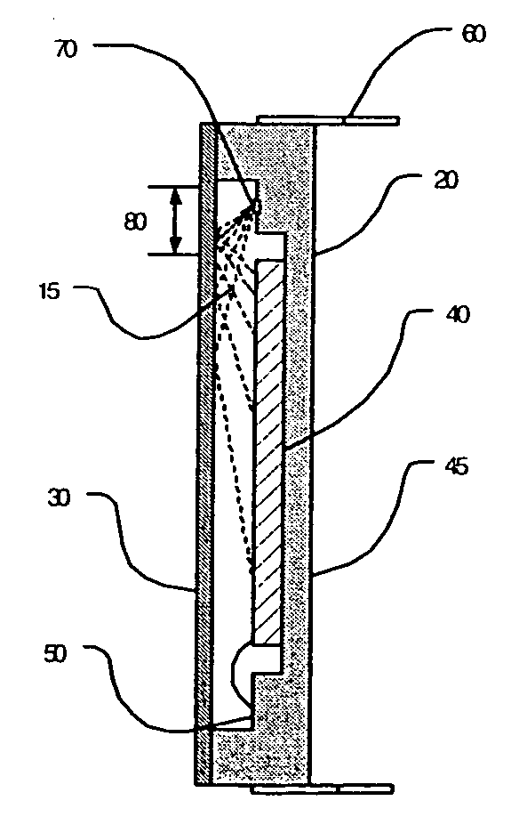
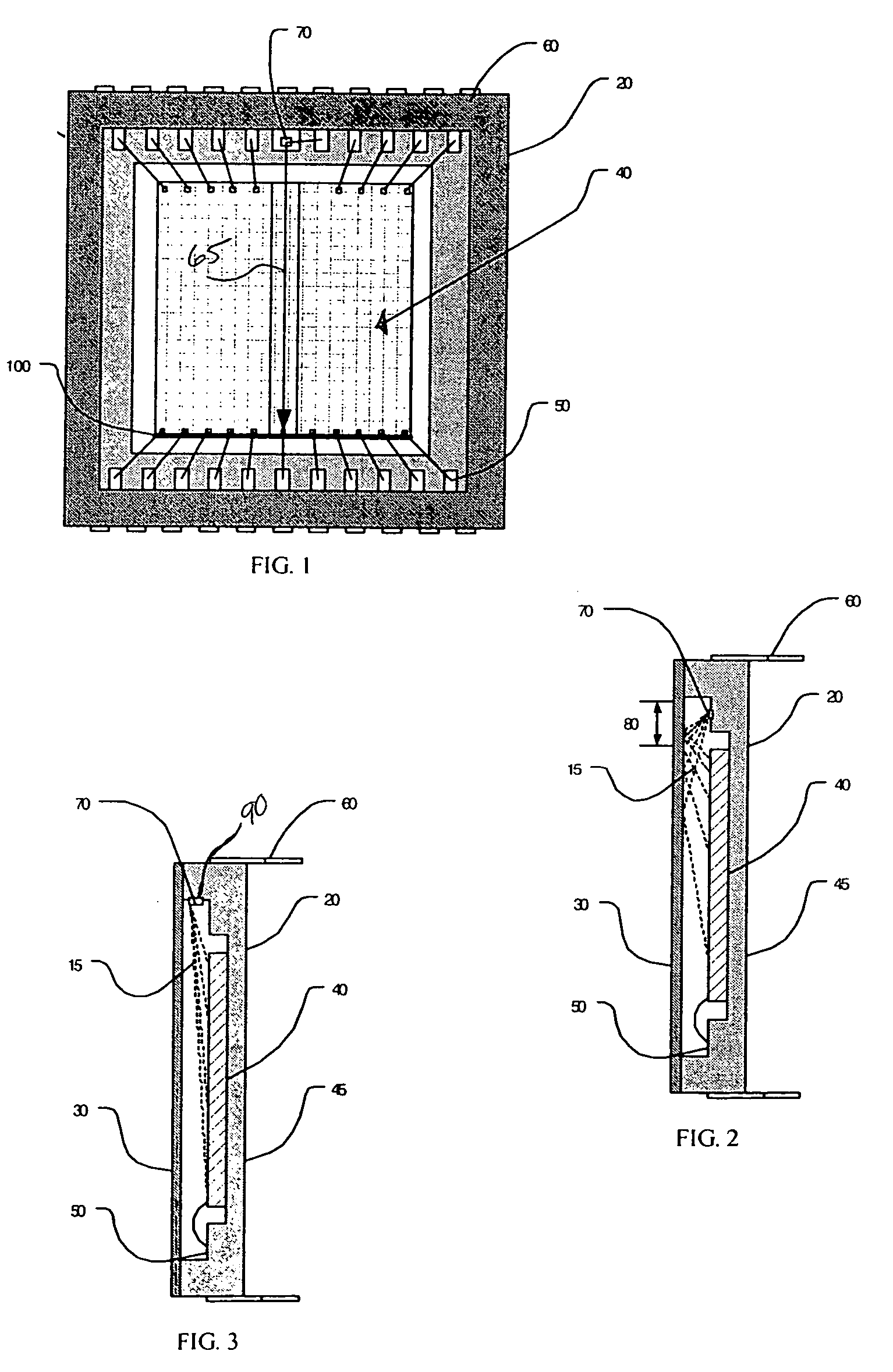
[0011] Referring to FIG. 1, there is shown a sensor package 10 having a hollowed out housing 20 having a cover glass 30 over an open portion on the housing 20. An image sensor 40 is disposed in a bottom portion 45 of the housing 20 and a plurality of bond pads 50 are disposed that extend through the housing 20 where they are connected to a plurality of pins 60. A LED 70 is preferably disposed near or substantially near a middle portion of one side of the housing 20. The LED 70 is connected to a pin 60 for power, and to ground via the bond pads 50.

[0012] Referring to FIGS. 1 and 2, to calibrate the image sensor 10, the LED 70 is energized for illuminating the image sensor 10. The light (illustrated by the dashed lines 15) from the LED 70 is reflected off the cover glass 30 at a plurality of oblique angles and back onto the image sensor 40. It is noted that a gradient is created since the light is reflected at various angles which redirects the light unevenly across the image sensor ...


PUM


Abstract

A method for calibrating a camera contemporaneously with image capture where the camera includes an image sensor with two or more output channels, the method includes the steps of providing two or more output channels that receive data from the image sensor; wherein the two or more output channels are respectively connected to two or more portions of the image sensor so that a boundary exists between the portions in a general direction; providing an illumination source that permits illumination of the image sensor substantially parallel to the general direction of the boundary so that creation of a gradient image is permitted in the image sensor; providing a measuring mechanism for permitting measurement of pixel values of the image sensor at a plurality of locations; providing a processor for permitting determination of a mapping function from the plurality of measured values; permitting mapping of pixels in each portion of the image sensor so that one or more pixel values are mapped to different pixel values based on the mapping function; and permitting applying the mapping function to an image captured in close temporal proximity to mapping the one or more pixels.

Description

FIELD OF THE INVENTION [0001] The invention relates generally to the field of calibrating image sensors, and more particularly, to a method for calibrating image sensors before each image capture. BACKGROUND OF THE INVENTION [0002] Currently, images are sometimes readout via two horizontal shift registers which permits images to be read out faster than from one shift register. These two registers inherently include a minor variation between them for which the image should be calibrated. Typically, image sensors are calibrated by capturing an image of a step wedge or step tablet that include a wide range of density patches. The image of the step tablet is used to create a mapping function that is used to match the response of the two outputs to each other. [0003] Although this is satisfactory, it includes drawbacks. One drawback is that manual calibration is undesirable due to time and financial constraints. Another drawback is that the conversion function changes with temperature an...

Claims


Application Information

Patent Timeline
Patent Type & Authority Applications(United States)
IPC IPC(8): H04N17/02H04N17/00
CPCH04N17/002
Inventor COPPOLA, STEPHEN M.COMPTON, JOHN T.
Owner EASTMAN KODAK CO
Why Eureka
Try Eureka