
Electric connector

A technology of electrical connectors and docking connectors, which is applied in the direction of connections, circuits, and parts of connecting devices, etc., can solve problems such as unstable butt joints of docking connectors, and achieve the effect of improving high-frequency transmission capabilities and reducing signal crosstalk

Inactive Publication Date: 2014-02-19
WENZHOU YIHUA CONNECTOR
View PDF5 Cites 28 Cited by
  • Summary
  • Abstract
  • Description
  • Claims
  • Application Information

AI Technical Summary

Benefits of technology

The electric connectors described by this new design have two separate grounds that are connected through an insulating material called ground sheets between them. By doing this they reduce interference from signals transmitted over different paths or frequencies simultaneously without affecting their quality level.

Problems solved by technology

This patented describes different designs for improving the performance of electric connectors used during high frequency signals transmitting through cables or wires. These improvements aimed towards better isolation between two rows of terminal elements while also allowing stable connection without instability caused by low spring forces.

Method used


Image

  • Electric connector
  • Electric connector
  • Electric connector

Examples


Embodiment Construction

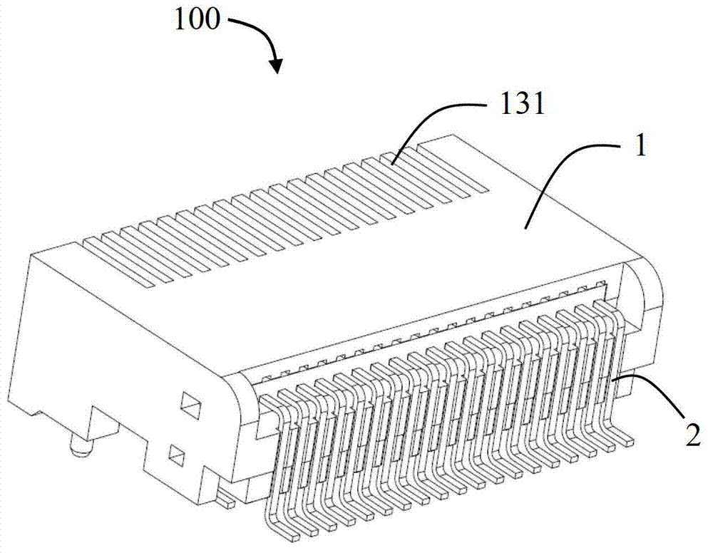
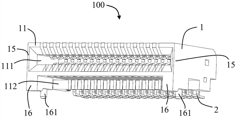
[0028] Please refer to figure 1 and figure 2 As shown, the present invention discloses an electrical connector 100 , which includes an insulating body 1 and a plurality of conductive terminals 2 installed in the insulating body 1 . In the illustrated embodiment, the electrical connector 100 is a QSFP (Quad Small Form-factor Pluggable) board connector, which is used to cooperate with a mating connector (not shown) for data transmission. The conductive terminals 2 can be installed in the insulating body 1 by direct insertion, or installed in the insulating body 1 in the form of a terminal module (details will be described later).

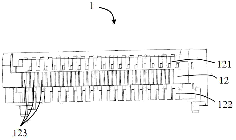
[0029] Please refer to Figure 1 to Figure 4 As shown, the insulating body 1 includes a mating surface 11, a rear surface 12 opposite to the mating surface 11, a first receiving chamber 111 penetrating through the mating surface 11, and a second housing chamber 111 penetrating through the mating surface 11 and located below the first housing chambe...


PUM


Abstract

The invention discloses an electric connector which is applied to a connector comprising a spring terminal and is especially suitable for a QSFP. The electric connector comprises an insulation body and a plurality of conductive terminals installed in the insulation body, wherein the insulation body comprises a butt joint surface and a first accommodation cavity penetrating the butt joint surface; the plurality of conductive terminals comprise a plurality of first conductive terminals disposed in an upper row and a plurality of second conductive terminals disposed in a lower row; the first conductive terminals comprise a plurality of first grounding terminals and a plurality of first signal terminals; and the second conductive terminals comprise a plurality of second grounding terminals and a plurality of second signal terminals. The electric connector further comprises a grounding sheet connoting the first grounding terminal and the second grounding terminals. By such arrangements, the first grounding terminals and the second grounding terminals are connected so that the potential difference of each grounding terminal is o, the crosstalk is reduced and the high-frequency transmission capability is improved.

Description


Claims


Application Information

Patent Timeline
Owner WENZHOU YIHUA CONNECTOR
Learn More