Electrical connector assembly

A technology of electrical connectors and connectors, which is applied in the direction of connection, two-part connection devices, parts of connection devices, etc., can solve the problems of poor grounding effect, long duration and overvoltage, unfavorable electrical connectors and related electrical equipment. Use and other issues

Active Publication Date: 2019-11-26
DEYI PRECISION ELECTRONIC IND CO LTD PANYU
View PDF8 Cites 4 Cited by
  • Summary
  • Abstract
  • Description
  • Claims
  • Application Information

AI Technical Summary

Problems solved by technology

[0003] When the plug and the socket are electrically connected, only the grounding terminal of the plug and the grounding terminal of the socket are in contact to form a grounding loop, resulting in a long grounding loop path and poor grounding effect. A new problem arises between the socket terminals, a large resonance will occur between the socket terminals and the socket intermediate shield, and the resonance often causes a long-lasting overvoltage, resulting in the The electrical connectors and related electrical equipment are prone to burnout, damage and other harmful phenomena, which is not conducive to the safe and stable long-term use of electrical connectors and related electrical equipment

Method used


Image

  • Electrical connector assembly
  • Electrical connector assembly
  • Electrical connector assembly

Examples


Embodiment Construction

[0052] In order to facilitate a better understanding of the purpose, structure, features, and effects of the present invention, the present invention will now be further described in conjunction with the accompanying drawings and specific embodiments.

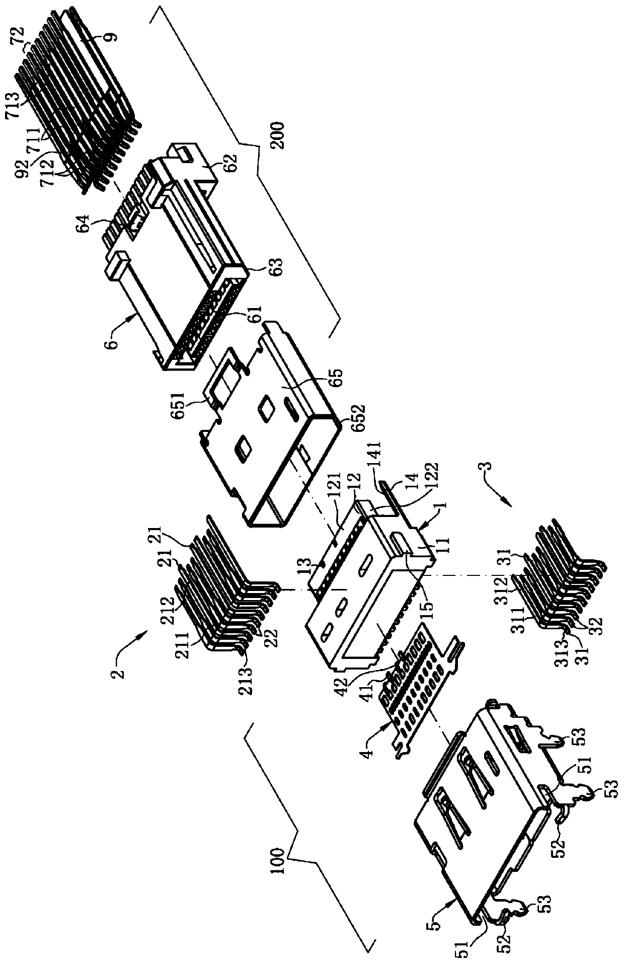
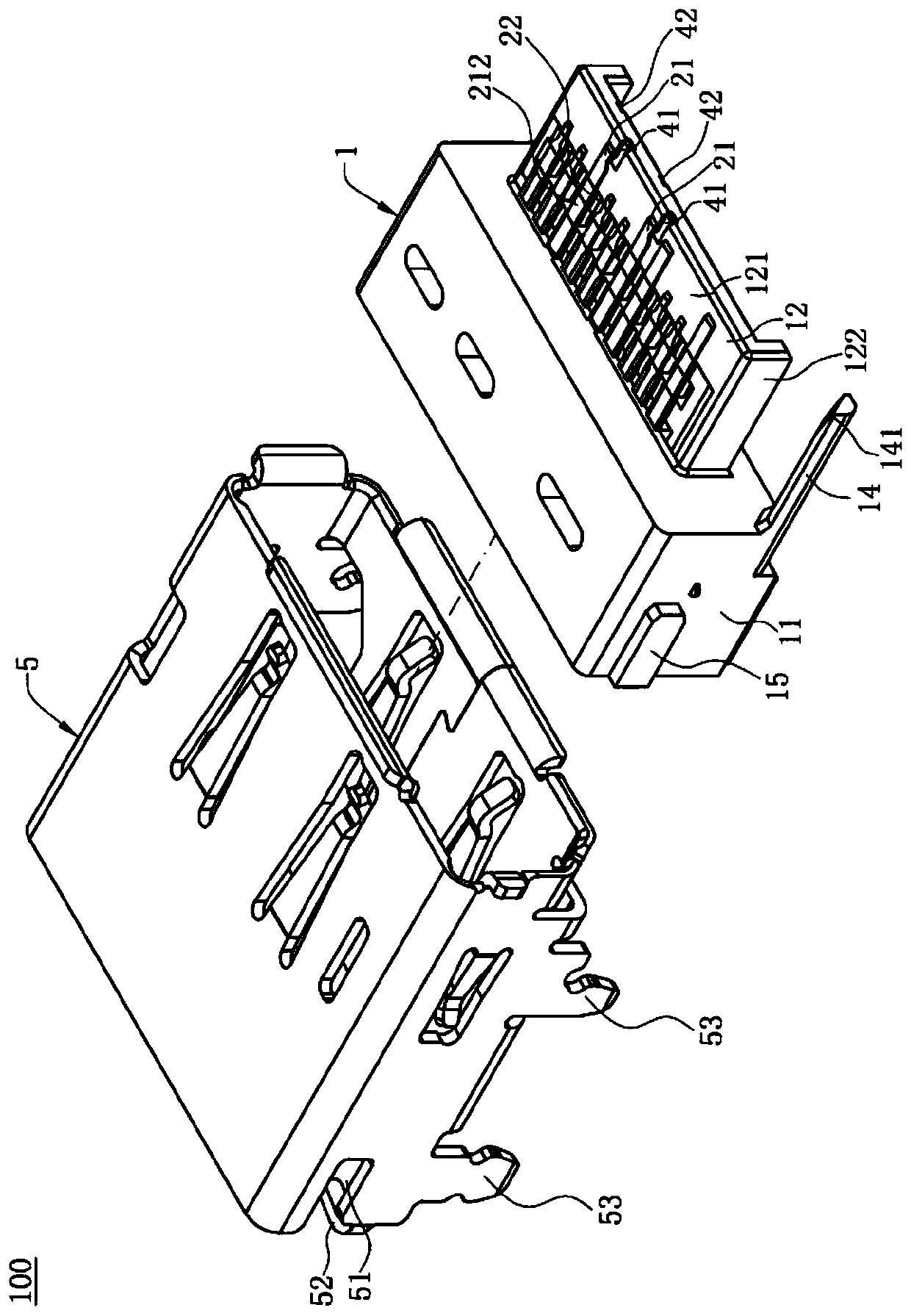
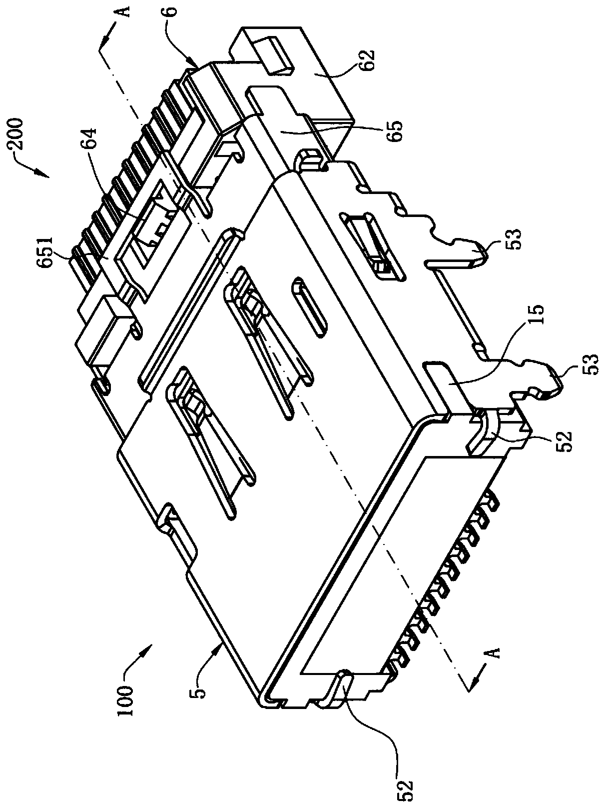
[0053] Please refer to figure 1 , which is the first embodiment of the electrical connector combination of the present invention, the electrical connector combination is a DisplayPort connector, which includes a first connector 100 and a second connector 200 docked with the first connector 100 , defining the direction in which the first connector 100 and the second connector 200 are docked is the front-to-back direction, the front end of the first connector 100 is correspondingly docked with the front end of the second connector 200, and the first A connector 100 is used for soldering to a circuit board (not shown), and the second connector 200 is used for connecting with a plurality of wires (not shown). The first connector 1...


PUM


Abstract

The invention discloses an electrical connector assembly. The electrical connector assembly comprises a first connector, an intermediate shielding sheet arranged on a first insulating body and locatedbetween two rows of first terminal groups, a second connector, an intermediate iron sheet arranged on a second insulating body and located between two rows of second terminal groups, wherein the intermediate iron sheet comprises a main body part, and at least one elastic abutting joint portion and at least one abutting portion are bent and extended from the main body portion in a vertical direction; the elastic abutting portion is located in front of the abutting portion, and the abutting portion abuts against the second ground terminal to form a ground loop, and enhance the grounding effectof the electrical connector assembly; when the second connector is in butt joint with the first connector, the second ground terminal is in contact with a first ground terminal, the elastic abutting joint portion elastically abuts against the intermediate shielding sheet or the first grounding terminal in the vertical direction, so that resonance generated by the intermediate shielding sheet and the intermediate iron sheet is effectively eliminated, the signal transmission efficiency and quality of the electrical connector assembly are improved, and safety guarantee is provided for the use ofthe electrical connector assembly and electrical equipment thereof.

Description

【Technical field】 [0001] The invention relates to an electrical connector combination, in particular to an electrical connector combination with an intermediate shielding sheet and a middle iron sheet. 【Background technique】 [0002] With the development of technology in the electronic product industry, the quality requirements for signal transmission of electrical connectors are getting higher and higher. The existing Display Port connector combination includes a plug and a socket, the plug includes a plug insulating body and two rows of plug terminals fixed on the plug insulating body, and the socket is provided with two rows of socket terminals fixed on the socket insulating body and An intermediate shielding sheet, the intermediate shielding sheet is embedded in the insulating body of the socket, and when the plug and the socket are butted, the plug terminal and the socket terminal are in contact, thereby completing the connection between the plug and the socket. electr...

Claims


Application Information

Patent Timeline
Patent Type & Authority Applications(China)
IPC IPC(8): H01R13/6461H01R13/6585H01R13/6597H01R13/6582H01R13/652H01R13/02H01R13/502H01R24/00
CPCH01R13/02H01R13/502H01R13/6461H01R13/652H01R13/6582H01R13/6585H01R13/6597H01R24/00
Inventor 秦大争蔡伦隆权
Owner DEYI PRECISION ELECTRONIC IND CO LTD PANYU
Why Eureka
Try Eureka