Automatic nailing device

An automatic and conveying device technology, which is applied in the direction of nailing tools, staple nailing tools, manufacturing tools, etc., to achieve the effect of improving production efficiency

Active Publication Date: 2014-02-26
GUANGZHOU HOMEBON WOOD MFG +1
View PDF11 Cites 18 Cited by
  • Summary
  • Abstract
  • Description
  • Claims
  • Application Information

AI Technical Summary

Problems solved by technology

[0005] In view of the defects of the existing floor nailing process, the purpose of the present invention is to provide an automatic nailing device, which can realize automatic nailing of the floor, effectively ensure the quality of the floor and improve the production efficiency

Method used


Image

  • Automatic nailing device
  • Automatic nailing device

Examples


Embodiment

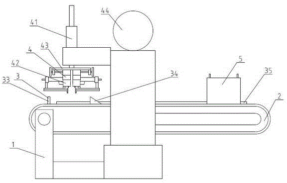
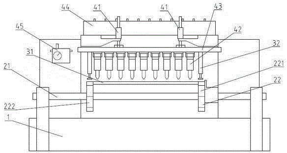
[0021] As shown in the figure: an automatic nailing device, including a fuselage 1, a transmission device 2, a positioning device 3 and a nailing device 4, the transmission device 2 includes a transmission shaft 21 and a transmission chain 22, and the transmission chain 22 is set On the transmission shaft 21, the transmission shaft 21 is arranged on the fuselage 1, the transmission shaft 21 is driven by a motor, and the positioning device 3 includes a support plate 31, a first cylinder 32, a fixed card 33, Movable card 34 and backing plate 35, described support plate 31 is perpendicular to the conveying direction of described transmission chain 22, and described support plate 31 is arranged on the described fuselage 1, and described first cylinder 32 is arranged on described support plate 31, the fixed card 33 is arranged on the body 1 on one side of the conveying device 2, and the movable card 34 is arranged on the other side of the conveying device 2 corresponding to the fixe...


PUM


Abstract

An automatic nailing device comprises a machine body, a conveying device, a positioning device and a nailing device. The conveying device comprises a transmission shaft and a conveying chain, the conveying chain is arranged on the transmission shaft, and the transmission shaft is arranged on the machine body. The positioning device comprises a supporting plate, a first cylinder, a fixed clamp, a movable clamp and a backup plate, wherein the supporting plate is vertical to the conveying direction of the conveying chain and is arranged on the machine body, the first cylinder is arranged above the supporting plate, the fixed clamp is arranged on the machine body on one side of the conveying device, the movable clamp and the fixed clamp are correspondingly arranged on the machine body on the other side of the conveying device, the movable clamp can move in the conveying direction of the conveying chain, and the backup plate is parallel with the conveying chain and is arranged on the machine body. The nailing device is arranged on the side where the fixed clamp is located and above the conveying device. According to the automatic nailing device, a floor can be automatically nailed, manual operations are replaced, production efficiency is greatly improved, and the automatic nailing device belongs to the technical field of floor production.

Description

technical field [0001] The invention relates to an automatic nailing device, in particular to an automatic nailing device used in the production of floor boards, and belongs to the technical field of floor production and processing. Background technique [0002] Geothermal heating technology has been widely used in Europe and North America since the 1950s. Geothermal heating is currently the most comfortable, healthy and increasingly popular heating method in the world. [0003] Due to the advantages of geothermal heating, it is welcomed by more and more users, and its application is becoming more and more common. Floor manufacturers have launched various types of geothermal flooring. At present, there are many types and structures of geothermal flooring, but due to the limitation of production equipment, there is a contradiction between the heat conduction effect and mass production of geothermal flooring. [0004] In order to better conduct heat from the floor upwards, g...

Claims


Application Information

Patent Timeline
Patent Type & Authority Applications(China)
IPC IPC(8): B27F7/02B27F7/09
Inventor 夏朝彦蔡尚郑敏金涛肖树彬
Owner GUANGZHOU HOMEBON WOOD MFG
Why Eureka
Try Eureka