Locking mechanism

A technology of locking mechanism and locking parts, which is applied to the packaging of vulnerable items, internal accessories, and types of packaged items. It can solve problems such as unstable road conditions, damage to ultrasonic equipment, and complex structures, so as to avoid shaking or falling down and improve performance. The effect of stability and simple structure

Active Publication Date: 2014-02-26
吴江科技创业园管理服务有限公司
View PDF6 Cites 5 Cited by
  • Summary
  • Abstract
  • Description
  • Claims
  • Application Information

AI Technical Summary

Problems solved by technology

[0002] Due to the irregular shape of the existing ultrasonic equipment, it is easy to shake or even fall due to unstable road conditions during transportation or moving, causing varying degrees of damage or even scrapping to the ultrasonic equipment
In order to improve the problem of ultrasonic equipment being damaged during transportation or moving, the industry has designed a locking mechanism to lock the ultrasonic equipment, but the structure is complex, and multiple steps are required for locking and unlocking actions, which is inconvenient for users to operate

Method used


Image

  • Locking mechanism
  • Locking mechanism
  • Locking mechanism

Examples


Embodiment Construction

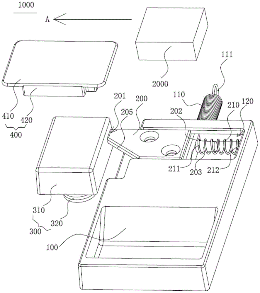
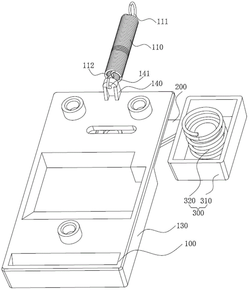
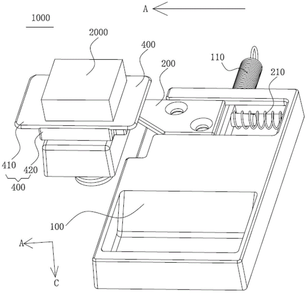
[0025] Please refer to figure 1 , figure 2 , figure 1 It is a front perspective schematic view of the locking mechanism of the present invention; figure 2 It is a perspective view of the bottom surface of the locking mechanism of the present invention. The locking mechanism 1000 of the present invention is used to lock the device 2000 to be locked. The locking mechanism 1000 includes a base 100 , a locking member 200 , at least one first elastic member 210 , and a supporting member 400 . It should be noted that, for the convenience of explanation, figure 2 The supporting member 400 is not shown in the figure.

[0026] The base 100 has a first side 130 , and the first sliding rail 120 is disposed on the base 200 . The locking member 200 is disposed on the first sliding rail 120 and can move back and forth in a first direction A relative to the base 100 along the first sliding rail 120 . The locking member 200 has a first end 201 and a second end 202 opposite to each ot...


PUM


Abstract

The invention relates to a locking mechanism used for locking a to-be-locked device. The locking mechanism comprises a base, a locking part, at least one first elastic part and a bearing part. The base is provided with a first side face and a first sliding rail. The locking part can move relatively to the base along the first sliding rail. Two ends of each first elastic part are butted against a second end portion of the locking part and the base. The bearing part allows the to-be-locked device to be fixed thereon and is provided with a first groove. During locking, the first elastic parts provides tension in a first direction to enable a first end portion of the locking part to protrude over the first side face and be inserted into the first groove; during unlocking, force is applied to allow the first elastic parts to be compressed and drive the locking part to move vertically along a second direction until the first end portion is separated form the first groove, and the second direction is opposite to the first direction. The locking mechanism can realize locking by depending on gravity of the to-be-locked device; through the design of a first corner and a second groove, one-man operation is facilitated, and the to-be-locked device is prevented from shaking or tumbling during transportation or movement.

Description

technical field [0001] The present invention relates to a locking mechanism, in particular to a locking mechanism for preventing a device to be locked from shaking or falling during transportation or moving. Background technique [0002] Due to the irregular shape of the existing ultrasonic equipment, it is easy to shake or even fall due to unstable road conditions during transportation or moving, causing varying degrees of damage or even scrapping to the ultrasonic equipment. In order to improve the problem of ultrasonic equipment being damaged during transportation or moving, some locking mechanisms have been designed in the industry to lock the ultrasonic equipment. However, the structure is complicated, and multiple steps are required for locking and unlocking actions, which is inconvenient for users to operate. Therefore, designing a locking mechanism with a simple structure and easy operation has become the direction of the industry's efforts. Contents of the inventi...

Claims


Application Information

Patent Timeline
Patent Type & Authority Applications(China)
IPC IPC(8): B65D85/30B65D25/10
Inventor 李国荣陈志宏
Owner 吴江科技创业园管理服务有限公司
Why Eureka
Try Eureka