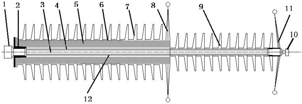
Lightning arrester with performance of line insulator

A line insulation and lightning arrester technology, applied in the field of lightning arresters with line insulator performance, can solve the problems of increased system failure rate, increased line and tower load, inconvenience, etc., achieve the best equipment size and performance indicators, and optimize the system installation method , The effect of reducing the failure rate of the system

Inactive Publication Date: 2014-02-26
STATE GRID CORP OF CHINA +2
View PDF7 Cites 2 Cited by
  • Summary
  • Abstract
  • Description
  • Claims
  • Application Information

AI Technical Summary

Problems solved by technology

However, in the prior art method, due to the large weight and volume of the arrester, not only the load on the line and the iron tower is increased, and the line facilities are complicated, but also because the position of the iron tower cross arm is limited, the installation of the arrester is extremely inconvenient. More equipment will also bring inconvenience to live work and other work
In addition, due to the parallel use of two independent devices, the total number of devices in the system is obviously doubled, resulting in a significant increase in the failure rate of the system, which makes the operation and maintenance workload of the transmission line heavy.
[0005] Although there are still a few studies in the prior art that hope to realize the integration of insulators and arresters, the actual effect is either to slightly improve the withstand voltage performance of the insulator at the expense of shape and stability, or to slightly improve the insulator’s service life. The carrying capacity of the arrester can only be used as an insulator or arrester in a slightly harsh environment, and it is completely impossible to have both functions at the same time
Most typically, the common problems of existing research are: the connection between the fittings at both ends and the mandrel is generally glued or screwed. Due to problems in the connection method and materials, it cannot withstand strong tensile loads, and the seal is also affected. Severe test, can not really achieve both the function of the insulator and the function of the lightning arrester; in addition, the structural height of the equipment is much higher than that of ordinary line insulators

Method used


Image

  • Lightning arrester with performance of line insulator

Examples


Embodiment Construction

[0026] The following will clearly and completely describe the technical solutions in the embodiments of the present invention with reference to the drawings in the embodiments of the present invention. Apparently, the described embodiments are preferred implementation modes for implementing the present invention, and the description is for the purpose of illustrating the general principle of the present invention, and is not intended to limit the scope of the present invention. The scope of protection of the present invention should be defined by the claims. Based on the embodiments of the present invention, all other embodiments obtained by those of ordinary skill in the art without creative efforts belong to the protection of the present invention. range.

[0027] At present, the line insulators in high-voltage transmission lines are generally porcelain insulator strings, glass insulator strings or composite insulators. Among them, the porcelain insulator string and the gla...


PUM

PropertyMeasurementUnit
tensile strengthaaaaaaaaaa

Abstract

The invention relates to the technical field of power transmission equipment, and discloses a lightning arrester with the performance of a line insulator. The lightning arrester comprises an iron tower side fitting, a mandrel, a wire side fitting and a hollow gapped lightning arrester body, wherein the iron tower side fitting and the wire side fitting are pressed on the two ends of the mandrel respectively; the hollow gapped lightning arrester body is sleeved outside the mandrel. According to the lightning arrester, functions of the insulator and the lighting arrester are simultaneously realized under the condition of structural height equivalent to that of an ordinary insulator string; the lighting arrester has a relatively good equipment dimension and good performance indexes.

Description

technical field [0001] The invention relates to the technical field of power transmission equipment, in particular to a lightning arrester with the performance of a line insulator. Background technique [0002] Transmission lines, especially high-voltage transmission lines, need to pay attention to many problems during the overhead laying process, the most common of which are line support, line insulation and overvoltage protection. In order to solve these problems, insulators are used in the prior art to solve the problems of supporting wires and preventing current from returning to the ground, and lightning arresters are used to protect transmission lines and electrical equipment from damage caused by atmospheric overvoltage (usually lightning strike) and operating overvoltage. [0003] Due to the different purposes of the two devices, the performance indicators they pay attention to are quite different. Among them, the insulator is mainly to stretch the line on the suppo...

Claims


Application Information

Patent Timeline
Patent Type & Authority Applications(China)
IPC IPC(8): H01B17/46H02G13/00
Inventor 李孟兴侯力枫庞博刘健武荣伟王树军季宁王钰孙红华程大印高丰
Owner STATE GRID CORP OF CHINA
Why Eureka
Try Eureka