Optical receiver for multimode communications

An optical receiver, multi-mode communication technology, applied in the direction of electromagnetic receiver, multi-mode transmission, optical fiber transmission, etc.

Active Publication Date: 2014-02-26
ALCATEL LUCENT SAS
View PDF6 Cites 16 Cited by
  • Summary
  • Abstract
  • Description
  • Claims
  • Application Information

AI Technical Summary

Problems solved by technology

In long-distance applications, such delays can exceed the processing depth capabilities of conventional digital signal processors

Method used


Image

  • Optical receiver for multimode communications
  • Optical receiver for multimode communications
  • Optical receiver for multimode communications

Examples


example 1

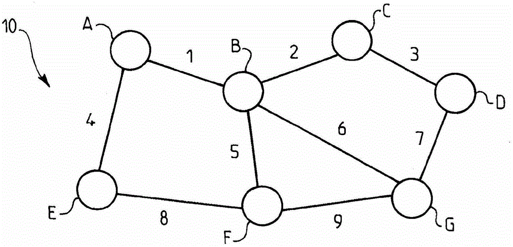
[0059] Example 1: Two modulated optical signals are sent from node A to node G via two modes LP01 and LP11. Propagate the two modes through spans 1 and 6 in that order. The resulting delay between the two modes is (see Table 2):

[0060] (50*4.25+80*2.5)=412.5ns.

example 2

[0061] Example 2: Three modulated optical signals are sent from node A to node G through three modes LP01, LP11 and LP02. All patterns are propagated through spans 1, 5 and 9 in that order because routing through span 6 is not available, eg span 6 does not support pattern LP02.

[0062] The resulting delay for LP11 is (see Table 2):

[0063] (50*4.25+50*4.25+60*4.22)=678.2ns.

[0064] The resulting delay for LP02 is (see Table 2):

[0065] (50*6.32+50*6.28+60.6.31)=10008.6ns.

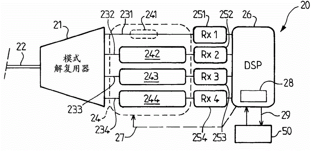
[0066] In one embodiment, delay control module 28 can also perform an update function for updating the lookup table in database 50 as indicated by arrow 29 . The data in Table 2 can be updated in several ways.

[0067] In one embodiment, the DSP 26 algorithmically determines the physical parameters upon receipt of a pre-known training sequence. Any modulation format can be used for this purpose. Such an update using data-aided algorithms is performed over time, for example weekly or monthly accord...


PUM


Abstract

An optical receiver (20) for multimode communications comprises: a mode demultiplexer (21) having an input connected to a multimode link (22) and a plurality of output lines (231-234), wherein the mode demultiplexer is adapted to couple each of the modal components of the optical signal substantially into a selected one of the output lines, a plurality of coherent optical detectors (251-254) respectively connected to the output lines to produce a set of electrical digital signals each comprising an in-phase component and a quadrature-phase component, a plurality of independently adjustable optical delay devices (241-244) arranged on the output lines to impart a selected delay to each of the corresponding modal components, and a signal processing device (26) adapted to process the digital signals to recover the independent modulations of the respective modal components by inverting a mode-mixing characteristic of the multimode link.

Description

technical field [0001] The present invention relates to the technical field of optical communication systems employing waveguides supporting more than one propagation mode, and in particular to optical receivers suitable for such systems. Background technique [0002] A potentially breakthrough solution for further increasing capacity in long-distance optical transmission systems is to exploit more than one spatial propagation mode in optical fibers. Such mode-division multiplexing enables multiple-input multiple-output (MIMO) transmission. WO-A-2010 / 151432 discloses an example of such an optical multimode transmission system. In optical multimode transmission systems, different spatial modes have different propagation constants and arrive at the receiver side with a time delay. This delay is a function of transmission distance and differential mode group delay (DMGD). In long-distance applications, such delays can exceed the processing depth capabilities of conventional ...

Claims


Application Information

Patent Timeline
Patent Type & Authority Applications(China)
IPC IPC(8): H04B10/2581H04J14/04
CPCH04B10/2581H04J14/04H04B10/60H04B10/616
Inventor C·克贝尔M·萨尔西
Owner ALCATEL LUCENT SAS
Why Eureka
Try Eureka