
Assistant device used for winding mechanism and capable of storing and releasing rotation energy

A booster device and energy technology, which is applied in door/window protection devices, building components, building structures, etc., can solve the problems of reducing production efficiency, increasing costs, and cumbersome assembly, so as to improve production efficiency, reduce production costs, and simultaneously The effect of high axis

Active Publication Date: 2014-03-12
KUSN HUANGTIAN AUTO PARTS INDAL
View PDF5 Cites 4 Cited by
  • Summary
  • Abstract
  • Description
  • Claims
  • Application Information

AI Technical Summary

Problems solved by technology

Therefore, the booster device of this structure needs to be equipped with a curtain box and installed in a pre-rotated state. The assembly is relatively cumbersome and laborious, which reduces production efficiency and increases costs.

Method used


Image

  • Assistant device used for winding mechanism and capable of storing and releasing rotation energy
  • Assistant device used for winding mechanism and capable of storing and releasing rotation energy
  • Assistant device used for winding mechanism and capable of storing and releasing rotation energy

Examples


Embodiment Construction

[0038] The present invention will now be further described in detail in conjunction with the accompanying drawings and embodiments. These drawings are all simplified schematic diagrams, only illustrating the basic structure of the present invention in a schematic manner, so it only shows the composition related to the present invention.

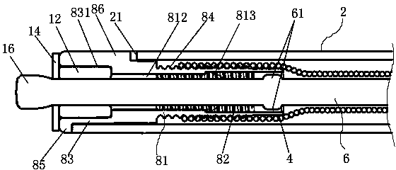
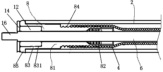
[0039] Such as Figure 1-10 As shown, a booster device for a retracting mechanism that can store and release rotational energy includes an inner tube 2, a bar-shaped core 6 accommodated in the inner tube 2, and a spring sleeved on the core 6 4. One end of the core iron 6 protrudes from the inner tube 2 and is sleeved with a spring ball 8 connected with the inner tube 2 . The spring ball 8 is a hollow structure with two ends open, and an axially extending screw thread 84 is provided on the outer wall. One end of the spring 4 is screwed on the spring ball 8 by means of a thread 84 , and the other end is connected with the core iron 6 . The c...


PUM


Abstract

The invention relates to an assistant device used for a winding mechanism and capable of storing and releasing rotation energy. The assistant device used for the winding mechanism and capable of storing and releasing the rotation energy comprises an inner pipe, core iron and a spring, wherein the core iron is of a strip shape and is contained in the inner pipe, the core iron is sleeved with the spring, one end of the core iron extends out of the inner pipe, and is sleeved with a spring bead which is connected with the inner pipe, one end of the spring is connected with the spring bead, and the other end of the spring is connected with the core iron. The assistant device used for the winding mechanism and capable of storing and releasing the rotation energy is characterized in that at least one protruding rib is arranged on the core iron, the radial direction of the protruding rib is outward, the spring bead comprises a first pipe portion, the internal radius of the first pipe portion is smaller than the radial distance between the outer end of the protruding rib and the central axis of the core iron, a guide groove is formed in the inner wall of the first pipe portion, is matched with the protruding rib in appearance, and extends in the axial direction, one end of the guide groove extends towards the interior of the inner pipe in the axial direction, and an opening is formed in the end portion of the first pipe portion. According to the assistant device used for the winding mechanism and capable of storing and releasing the rotation energy, due to the fact that on the basis of a traditional structure, the protruding rib on the core iron is used in cooperation with the guide groove in the spring bead, locking of pre-rotation energy of the spring can be easily achieved before the assistant device leaves the factory, a curtain box does not need to be added, assembly is convenient, production efficiency is improved, and the production cost is reduced.

Description

technical field [0001] The invention relates to components of a retraction mechanism. Background technique [0002] The take-up mechanism usually includes a booster device and a positioning device, which acts on belt-like or sheet-like soft materials, and is widely used in various industries, such as roll-up shades and sunshades. The shade is stored in the curtain box and is retracted by a retracting mechanism. The assisting device of the existing retracting mechanism mainly includes an inner tube for winding the shade, and a spring housed in the inner tube. In order to support the spring and control the deflection of the spring, a core iron is usually installed inside the spring. A spring bead is rotatably installed on one end of the core iron, wherein the spring bead is connected with one end of the spring, and the other end of the spring is fixed. Before use, the curtain is wound on the inner tube in advance in the factory, and the spring is pre-rotated, that is, the ro...

Claims


Application Information

Patent Timeline
Patent Type & Authority Applications(China)
IPC IPC(8): E06B9/56
Inventor 刘典昌
Owner KUSN HUANGTIAN AUTO PARTS INDAL
Learn More