Battery charger polarity self-adaption system
An adaptive system and battery charger technology, applied to battery circuit devices, current collectors, electric vehicles, etc., can solve problems such as explosions, damage to chargers, and battery scrapping
- Summary
- Abstract
- Description
- Claims
- Application Information
AI Technical Summary
Problems solved by technology
Method used
Image
Examples
Embodiment Construction
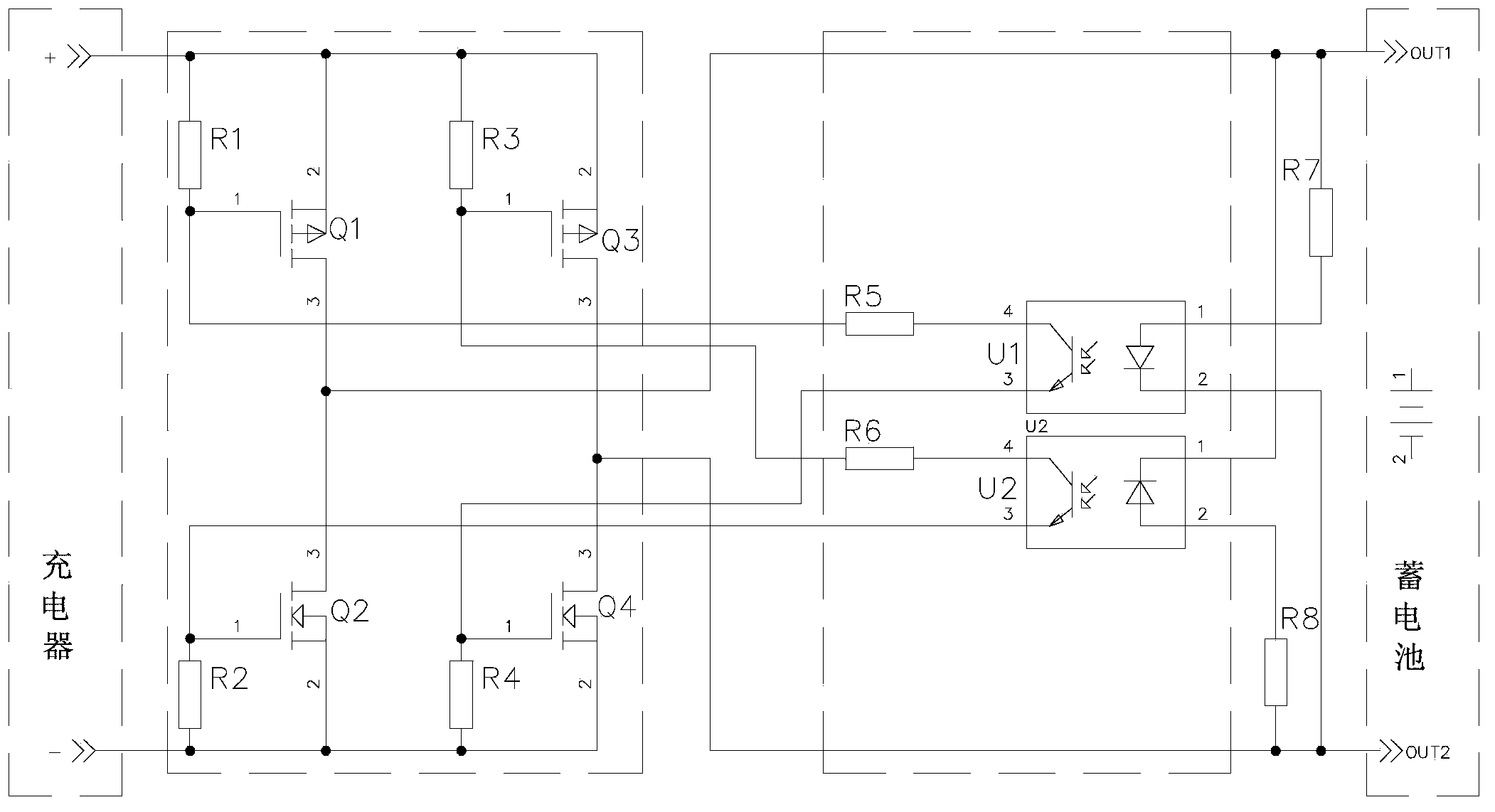
[0012] The battery charger polarity adaptive system of the present invention is arranged between the charger and the storage battery, and the system includes a control circuit and a controlled full-bridge circuit, and the control circuit and the controlled full-bridge circuit are connected through resistors R5 and R6;
[0013] Among them, the control circuit includes optocoupler U1, optocoupler U2, resistor R7, and resistor R8. Pin 1 of optocoupler U1 is connected to resistor R7 and then connected to both ends of the battery with pin 2, and pin 2 of optocoupler U2 is connected to resistor R8. Then connect the two ends of the battery with pin 1 respectively;
[0014] The controlled full-bridge circuit includes PMOS tube Q1, PMOS tube Q3, NMOS tube Q2, NMOS tube Q4, resistor R1, resistor R2, resistor R3, resistor R4, one end of resistor R1 and resistor R3 are respectively connected to one end of the charger, resistor R2 1. One end of resistor R4 is connected to the other end of ...
PUM
 Abstract
Description
Claims
Application Information
 - R&D
- Intellectual Property
- Life Sciences
- Materials
- Tech Scout
- Unparalleled Data Quality
- Higher Quality Content
- 60% Fewer Hallucinations
Browse by: Latest US Patents, China's latest patents, Technical Efficacy Thesaurus, Application Domain, Technology Topic, Popular Technical Reports.
© 2025 PatSnap. All rights reserved.Legal|Privacy policy|Modern Slavery Act Transparency Statement|Sitemap|About US| Contact US: help@patsnap.com

