
Driving assistance device

A driving assistance and moving body technology, applied in control devices, automatic starting devices, transportation and packaging, etc., can solve problems such as driver's sense of incongruity, reduction, and inability to calculate speed, and achieve the effect of ensuring safety.

Active Publication Date: 2014-03-12
TOYOTA JIDOSHA KK
View PDF6 Cites 8 Cited by
  • Summary
  • Abstract
  • Description
  • Claims
  • Application Information

AI Technical Summary

Problems solved by technology

Therefore, conventional driving assistance devices avoid collisions by judging whether there is a collision when traveling on the current predicted road, and cannot calculate how much to reduce the speed to avoid collisions, how much to dodge to avoid collisions, etc.
In addition, the collision judgment of conventional driving assistance devices largely depends on the prediction accuracy of the future position of the own vehicle.
Therefore, when the prediction accuracy decreases (for example, when the host vehicle is accelerating, decelerating, or steering), the accuracy of collision judgment may decrease.
In this case, the conventional driving assistance device may cause discomfort to the driver by performing unnecessary driving assistance or not performing driving assistance at the necessary timing.

Method used


Image

  • Driving assistance device
  • Driving assistance device
  • Driving assistance device

Examples


Embodiment Construction

[0026] Hereinafter, embodiments of the driving assistance device will be described with reference to the drawings.

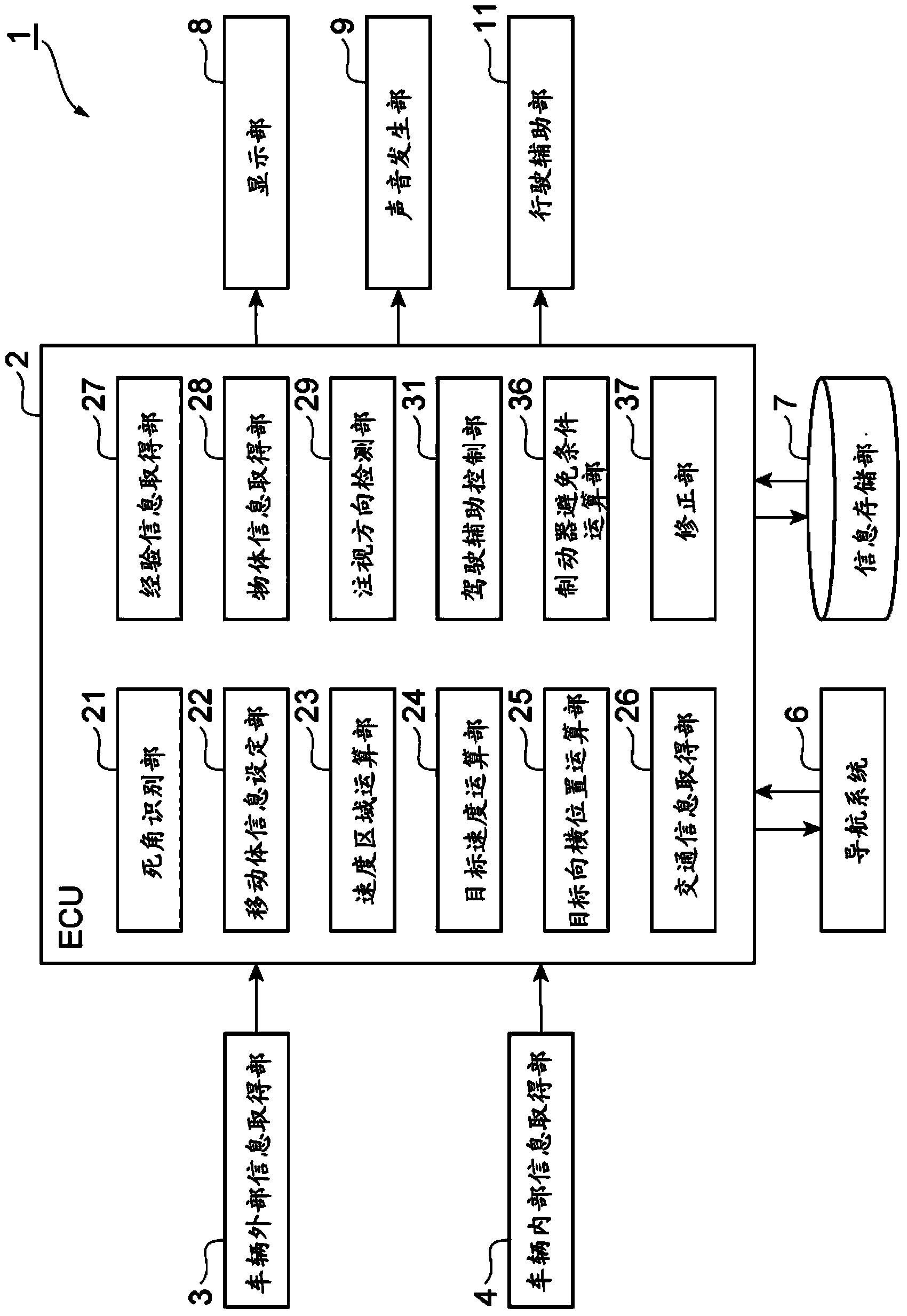
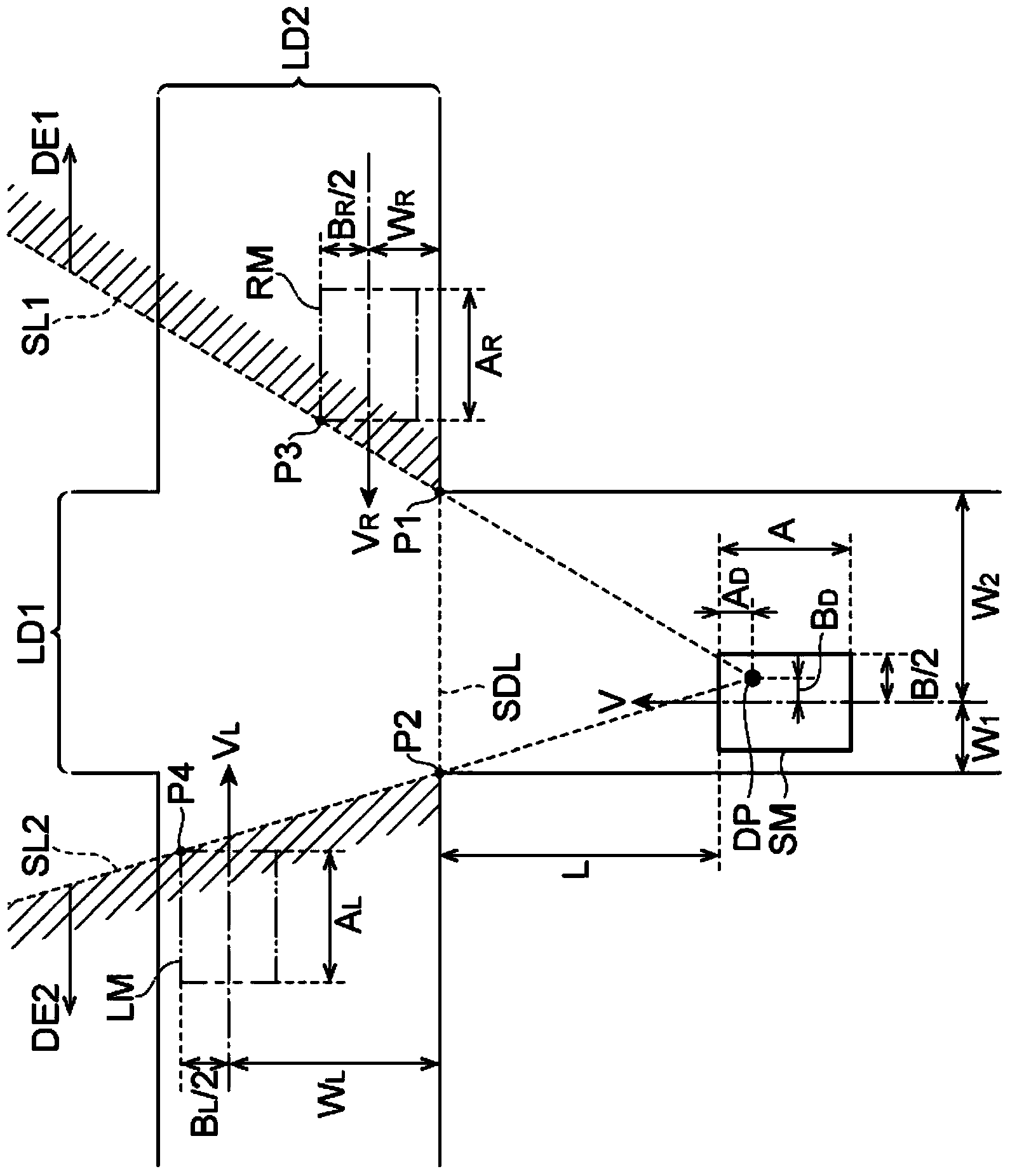
[0027] figure 1 It is a block configuration diagram of the driving assistance device according to the embodiment. figure 2 It is a figure which shows an example of the state immediately before host vehicle SM enters an intersection. exist figure 2 In the shown intersections, the lane on which the host vehicle SM travels is indicated by LD1 , and the lane crossing the lane LD1 is indicated by LD2 . exist figure 2 , it is assumed that the lane LD1 on which the host vehicle SM travels is the priority lane. It is assumed that structures such as walls, fences, and buildings are provided at least on both sides of the traffic lane LD1. At such intersections as figure 1 As shown, a dead spot DE1 is formed on the right side of the host vehicle SM, and a dead spot DE2 is formed on the left side of the host vehicle SM. The field of view of the driver DP in the ho...


PUM


Abstract

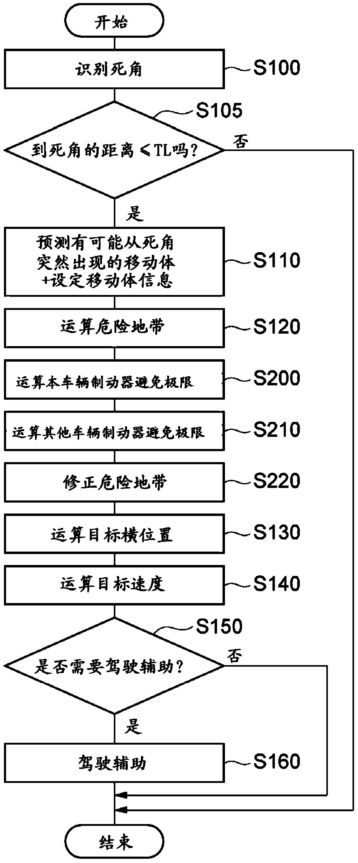
This driving assistance device is provided with: a blind spot recognition unit which recognizes a blind spot of a driver in the direction of travel of a vehicle; a moving body information configuration unit which configures moving body information, which includes at least the estimated speed of a moving body, as information regarding a moving body with the potential for darting out from a blind spot; a speed region calculation unit which calculates, on the basis of the moving body information configured by the moving body information configuration unit, a speed region for the vehicle in which there is a possibility of the vehicle making contact with a moving object coming from a blind spot when the vehicle advances in the direction of travel; a braking avoidance condition calculation unit which calculates a braking avoidance condition that enables contact with a moving body to be avoided as a result of the vehicle braking, and / or a braking avoidance condition that enables contact with the vehicle to be avoided as a result of the moving body braking; a speed region modification unit which modifies the speed region on the basis of the braking avoidance condition calculated by the braking avoidance condition calculation unit; and a target speed calculation unit which calculates a vehicle target speed on the basis of the speed region.

Description

technical field [0001] The invention relates to a driving assistance device. Background technique [0002] As a conventional driving assistance device, there is known a device that considers an object suddenly appearing from a blind spot when entering an intersection or the like, and performs driving assistance. For example, the driving assistance device in Patent Document 1 predicts the road ahead of the host vehicle, recognizes a blind spot for the driver in the traveling direction of the host vehicle, predicts an object that may suddenly appear from the blind spot, and detects whether the object can move. If the range overlaps with the predicted course of the host vehicle, it is determined that there is a possibility of collision, and driving assistance is performed to avoid the collision. [0003] Patent Document 1: Japanese Patent Laid-Open No. 2006-260217 [0004] However, conventional driving assistance devices perform driving assistance by using the predicted cours...

Claims


Application Information

Patent Timeline
IPC IPC(8): G08G1/16B60T7/22
CPCB60T2210/34G08G1/166B60W2720/10B60W30/09B60W2550/14B60W30/0953B60W10/184B60W30/095B60W30/18154B60W30/0956B60T7/22B60W2552/00B60W2554/00B60W2554/4041
Inventor 永田真一
Owner TOYOTA JIDOSHA KK
Learn More