Stamper punch for punching
A technology of punching and punching, which is applied in the field of die punching, can solve the problems that cannot be done, and achieve the effect of good punching effect and easy installation
- Summary
- Abstract
- Description
- Claims
- Application Information
AI Technical Summary
Problems solved by technology
Method used
Image

Examples
Embodiment Construction
[0014] Below in conjunction with accompanying drawing, the present invention is described in further detail:
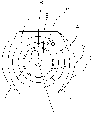
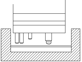
[0015] As shown in the figure: Die punch for punching, including shell 1, main pressure column 2, auxiliary pressure column 3, star pressure column 4, friction ring 5, axial punch 6, off-axis punch 7 , an auxiliary punch 8, a planetary punch 9, and an arc slot 10; a main pressure column 2 is arranged in the center of the housing 1, an auxiliary pressure column 3 is nested outside the pressure column 2, and a star pressure column 4 is nested outside the auxiliary pressure column 3; An axial punch 6 is arranged at the center of one end of the main pressure column 2, an off-axis punch 7 is arranged at a place far from the center of the axis punch 6, an auxiliary punch 8 is arranged at one end of the secondary pressure column 3, and an auxiliary punch 8 is arranged at one end of the star pressure column 4. Star Punch 9. The friction ring 5 is arranged between the main pr...
PUM
 Abstract
Description
Claims
Application Information
 - Generate Ideas
- Intellectual Property
- Life Sciences
- Materials
- Tech Scout
- Unparalleled Data Quality
- Higher Quality Content
- 60% Fewer Hallucinations
Browse by: Latest US Patents, China's latest patents, Technical Efficacy Thesaurus, Application Domain, Technology Topic, Popular Technical Reports.
© 2025 PatSnap. All rights reserved.Legal|Privacy policy|Modern Slavery Act Transparency Statement|Sitemap|About US| Contact US: help@patsnap.com