
Connecting device for insulating operating bar

A technology of insulating operating rods and connecting devices, which is applied in the direction of cable installation devices, cable installations, electrical components, etc., can solve the problems of single function of the operating rod and the inability to change the length of the operating rod, so as to avoid single function, improve repair time, Linking Simple Effects

Inactive Publication Date: 2014-03-19
何苍贵 +2
View PDF6 Cites 1 Cited by
  • Summary
  • Abstract
  • Description
  • Claims
  • Application Information

AI Technical Summary

Problems solved by technology

[0003] The present invention aims to solve the problems that the existing operating rods can only be used for one rod and one rod, resulting in a single function of the operating rod and the inability to change the length of the operating rod. The invention provides an insulating operating rod connection device

Method used


Image

  • Connecting device for insulating operating bar
  • Connecting device for insulating operating bar
  • Connecting device for insulating operating bar

Examples


specific Embodiment approach 1

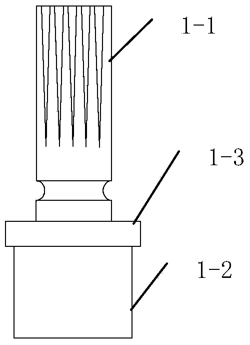
[0026] Specific implementation mode one: see Figures 1 to 9 Describe this embodiment, an insulated operating rod connection device described in this embodiment, which includes a spline type end connection part 1, two spring type end connection parts 2, an insulating operation rod 3 and a gear type The terminal connection part 4; the insulating operating rod 3 is a cylindrical structure,

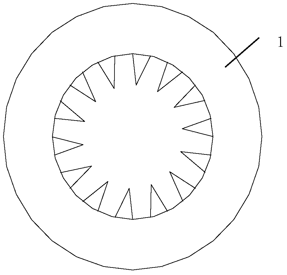
[0027] The splined end connection part 1 includes a first spline shaft 1-1 and a connecting shaft 1-2, the first spline shaft 1-1 and the connecting shaft 1-2 are coaxially connected and made into one structure, the diameter of the first splined shaft 1-1 is smaller than the diameter of the connecting shaft 1-2, and one end of the connecting shaft 1-2 connected to the first splined shaft 1-1 is provided with a shoulder 1-3, and the connecting shaft 1- The other end of 2 is inserted into one end of the insulating operating rod 3, and is fixedly connected with the insulating operating rod 3, ...

specific Embodiment approach 2

[0036] Specific implementation mode two: see Figures 1 to 9 This embodiment is described. The difference between this embodiment and the connecting device for an insulating operating rod described in Embodiment 1 is that the radial section of the boss 4 - 4 is rectangular.

specific Embodiment approach 3

[0037] Specific implementation mode three: see Figures 1 to 10 This embodiment is described. The difference between this embodiment and the connection device for an insulated operating rod described in Embodiment 1 or Embodiment 2 is that the surface of the cylindrical casing 2-6 is formed into a scale-like grid.


PUM


Abstract

The invention discloses a connecting device for an insulating operating bar and relates to the connecting field of various appliances which are operated through the insulating bar during maintaining of electric lines in an electric system. The connecting device for the insulating operating bar comprises a spline type end connecting component, two spring type end connecting components, the insulating operating bar and a gear type end connecting component, wherein two adjacent insulating operating bars are connected through one spline type end connecting component and one spring type end connecting component, so that the length of a combined operating bar is increased, connection between bars is simple, the number of carried tools is reduced; one end of the insulating operating rod is connected with the gear type connecting component through the other spring type end connecting component; the gear type end connecting component can be used for connecting a plurality of operating appliances. The connecting device for the insulating operating bar is mainly applied to the maintaining field of electric lines in the power system and solves the problems that the existing operating bar can only be used for one purpose and accordingly the operating bar function is single and the length of the operating bar cannot be changed.

Description

technical field [0001] The invention relates to the connection field of various appliances operated by insulating rods in the maintenance of power transmission and distribution lines in the power system. Background technique [0002] The insulating operating rod connection device is one of the indispensable operating tools in the maintenance work of power system transmission and distribution lines (including live work). During maintenance, the original operating rod can only be used for one rod and one use, and the work nature is single. If a multi-functional operating rod is involved, the connection between the rods will be simplified, and it can be combined into a 10KV-500KV insulating operating rod at will. , directly replacing the equipment that needs the end during operation will be a major new technology for power transmission and distribution maintenance work in the power system; and only need to replace the equipment at the end to complete various tasks in the work ...

Claims


Application Information

Patent Timeline
Patent Type & Authority Applications(China)
IPC IPC(8): H02G1/00
Inventor 何苍贵冯志仑金龙哲
Owner 何苍贵
Learn More